diy solar

diy solar

Building the sickest ® VAWT ever. Brilliant minds unite please!!

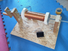
but my coil winder was tested and deemed useful.

Do you have a feed of wire for winding, and is it far enough away that the coil automatically distributes itself back and forth?
I could imagine using low RPM drill/driver to spin.
 
Do you have a feed of wire for winding, and is it far enough away that the coil automatically distributes itself back and forth?
I could imagine using low RPM drill/driver to spin.
please elaborate. I do have a master spool (a sick ass big one) hanging nearby.
I am just not grasping yet what it is you meant regarding the automatic distribution.

ANd yes sir, thanks for the drill suggestion. I am sure to make things more high geared once all the components have been deemed in order.
 
When winding thread on a bobbin (sewing machine) or cable on a winch, so long as spool feeding it is far enough away, the wire will be guided by previous turn to sit adjacent. When it hits end of bobbin, mandrill, whatever, it is pushed back and cycles over the previous layer.

Sometimes, last winding layer will slip down side and reach an earlier layer; for higher voltages e.g. above a few hundred, the enamel insulation isn't sufficient and fails. High voltage coils rely on incremental voltage between each layer of winding.

Another fault that has occurred is using fingers to tension 40 awg wire, resulting in it stretching and insulation failing. In that case, I felt hanging it with weight down a stair well might be better.

This is also done with a motorized/mechanized guide. But simpler if the line does that itself.


Spool too big-ass, and inertial + friction could apply too much resistance. In that case, a couple tensioner pullies to feed line gently and motorized big spool (or cut-out on winding motor) could avoid over-stress.
 
btw gang,

I have not been sitting still.

I came to a 36mm coil thickness not arbitrarily. I did measurements that me think that since copper wire is cheaper than magnets I might as well use more of it.

1687663211053.png

the field strength never reaches a totally unusable value.
Also I made sure to use at least 3 poles (6 magnets) for this test always measuring around the center pair.
 
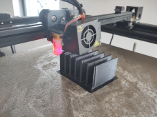
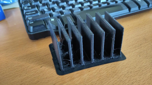
witness a single 3 phase coil holder in the making.

1687768894321.png

It has an inner radius of 60cm. and a height of 40mm with the top 2mm meant to be closed during curing with resin.

Now if I can fit 3 x 1100 winds @ 0.4mm diam in there then we're golden. The only thing I am aware of at this time that could go wrong then is that the setup does not handle the heat.

If I can't fit said amount of winds winds then i'll try 3 x 733 winds.
 
and I alreadty can imagine that the PLA will be the weak part.

But do not worry gang. This is called prototyping.

If I can get brutal wattage out of it for a short time before it is overheating. Then I know I am on the right track.
 
I tried 1100 winds. it broke my holder.

Then I tried 550 winds.

1687971622383.png

The only way I see to be able to 'stack' coils is to make them very large so that its easy to flatten them out.
 
I have no pictures for proof. but i have settled on 400 winds, making for a 800 wind per magnetic pair.

Don't worry gang I am still at it. making this seriously sick
 
this is now no longer a matter of what can be done on a small scale.

Now it is me trying to safe face against the long standing title of this thread.

hahahh I think I can do it. I am already planning to go even wider than 4m. I am thinking maybe 6m is better ;)
 
ohh I forgot to tell, I will replace most if not all steel aspects for aluminum.

sure it will be not without cost. But we have already crossed the point of no return when we think about the cost aspect.
 
I don't think you've set your VAWT sights big enough.

small steps brother. small steps

One of those steps is getting the coils right. I really would like some advice here.

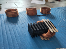
What we have here is 3 x 300 winds (I had to downgrade from 400 to 300 because of spacing issues) of 0.4mm enameled copper wire already on the holder. And another 3 x 300 winds waiting to be installed.
1695747253673.png

Now what would be the most effective way, that does not involve soldering, of tying those 0.4mm diam wires together? Keeping increase of resistance/loss of power potential in mind.
 
"Enamel" magnet wire in modern times is typically polyester.
No need to scrape off, nicking copper in the process.
Use a solder pot with flux, possibly a bit higher than normal temperature, to strip it.

Not sure, maybe some armatures terminate wire by crimp. I observed lack of solder color.
But yours isn't on an armature with commutator, and you're just connecting windings in series.
You might be able to use crimp terminal. I suspect polyester gets in the way (unlike native oxide on aluminum I see our utility PG&E crimp through.)
Solder seems like a reasonable way to go. But individually bare, possibly tinned, crimping could work too. Or maybe any of those solderless connectors, waygo etc. IDC is another possibility. Wire wrap? If it matches a tool size. But you'll need pins mounted some how.
 
my angst for soldering is multifold.
first most I suck at it. I might set my house on fire before I get any solder in place.
second I need to be able to change the connections with ease as mistakes can and will be made.
 
Back
Top