diy solar

diy solar

Can MPP and/or Growatt inverters be NEC code compliant?

Both the MPP and Growatt line of inverters have a few aspects that make me wonder if it is possible to make an NEC-compliant implementation.

1) Are they UL listed?
It looks to me that many (most?, all?) of the Growatt and MPP inverters to not have the proper UL ratings to meet the code. This alone could make it impossible to do an NEC code compliment install.

Has NEC kept up with current bybrid and off grid inverters? That is where the problem is, they really need to update the code to ensure the solar "market" is supplied with equipment that meets the requirements. Manufacturers will build it if NEC was to update.

As for UL, I think many manufacturers are not paying UL for testing based upon previous problems with UL engineers playing games. Other testing entities then test to the UL standard and the equipment passes. An example is TUVus certification, it meets the UL standard and is accepted. But have local inspectors been instructed on TUVus testing and certification? Again, we go back to NEC and it's lagging code changes as things move forward.

However, can you do an install that meets code in all other ways?..... I am not sure.

2) Can Ground Fault Protection be added?
Both brands make it clear that you should not ground the PV circuit. This means that you can not use the traditional PV ground fault protection of a breaker between PV negative and Ground. (This effectively grounds the PV circuit) The good news on this is that there are PV Ground Fault systems that use a differential current sensor (typically a hall effect sensor) to detect a ground fault and open the circuit. This detection method does not require grounding the PV circuit, but this type of ground fault system is expensive and hard to find.

EDIT: Corrected 60V to 50V.
3) How do you meet the requirement to ground DC circuits that operate over 50V? Almost all PV circuits for these systems will end up with at least 2 panels in series and that will almost always create circuits that operate at voltages above 50V. Since the NEC requires circuits that operate above 50V to be grounded, and the inverters say not to ground the PV circuits, how can this requirement be met?

What am I missing or misunderstanding? Are my concerns valid? Are there other areas of concern for NEC code compliance with these inverters?

Push on NEC for clarification. Plus look at Mike Holt's literature on grounding PV.

There are several threads that are dancing around this question so I thought it might be good to start this thread specifically about code compliance and these inverters.
List the code sections you have a problem with.
 
Good to know. I have never looked into it. Just from reading other posts, I thought that UL1741 was about rapid shutdown.
I guess that is what I get for assuming. lol
There is more of course, covered broadly here with Rule 21. https://www.cedgreentech.com/article/ul-1741-rule-21-advanced-inverter-tests

But really it boils down to if the unit disconnects from the grid thru a TS under inverter power, then backfeed won't occur and you wouldn't have to be concerned about fluctuating line voltages with many PV systems shutting down, then coming back online. I can see why this would be a concern, but the only aspects that apply for these off grid inverters for UL1741 in a local generation capacity is the disconnect from grid as these aren't grid interactive.
 
Not so sure about that. Take the GW 12000T. On AC input, only L1 and L2 are present. There is one ground terminal present. View attachment 89195
You are correct.... I can not say definitively that all of their inverters are the same. However, I go back to my assertion that the problems I am talking about are all on how to properly wire the Battery and PV circuits to meet code. What happens on the AC side is somewhat independent of the Battery and PV side of things. All the manuals seem to have the same warning about not grounding the PV circuit and that leads to the issues I listed above.
 
Looking at the GW12000T, the question then becomes how to wire it? Discussion is in this thread https://diysolarforum.com/threads/growatt-12k-passthrough.37359/

Considering N is tied to output side, most likely a N-G bond doesn't exist under inverter mode. But haven't heard any results of testing
I agree with your assessment of the AC N-G bond (including the fact that we have not heard testing results to confirm it). However, that does not address the concerns on the DC side.
 
Has NEC kept up with current bybrid and off grid inverters? That is where the problem is, they really need to update the code to ensure the solar "market" is supplied with equipment that meets the requirements. Manufacturers will build it if NEC was to update.
You and I are not on the same page on this. The two issues I have discussed don't really relate to the inverters. They relate to the safety of PV circuits.

1) The NEC requires Ground fault protection on PV circuits that are on or in a house..... And it appears to me that the Growatt and MPP inverters can only have a Ground Fault Detection circuit that uses a current-differential sensor (Like a Hall effect sensor). The more common breaker between PV- and Ground is not allowed according to the inverter documentation because it would ground the PV circuit.

2) The NEC requires any DC circuit running greater than 50V be a grounded circuit (Either the Positive or Negative must be tied to the earth grounding system). Almos all PV circuits with these inverters are going to have voltages north of 50V and therefore they must be grounded for safety purposes..... but the inverter manuals say the PV circuit must not be grounded.
 
The output ground (yellow/ green stripe wire), is connected to a pc board. Then another ground wire runs to the chasis ground. With the input ground.
That may or may not be an AC ground fault circuit, but it does not sound like it has anything to do with PV ground fault.
 
And it appears to me that the Growatt and MPP inverters can only have a Ground Fault Detection circuit that uses a current-differential sensor (Like a Hall effect sensor).
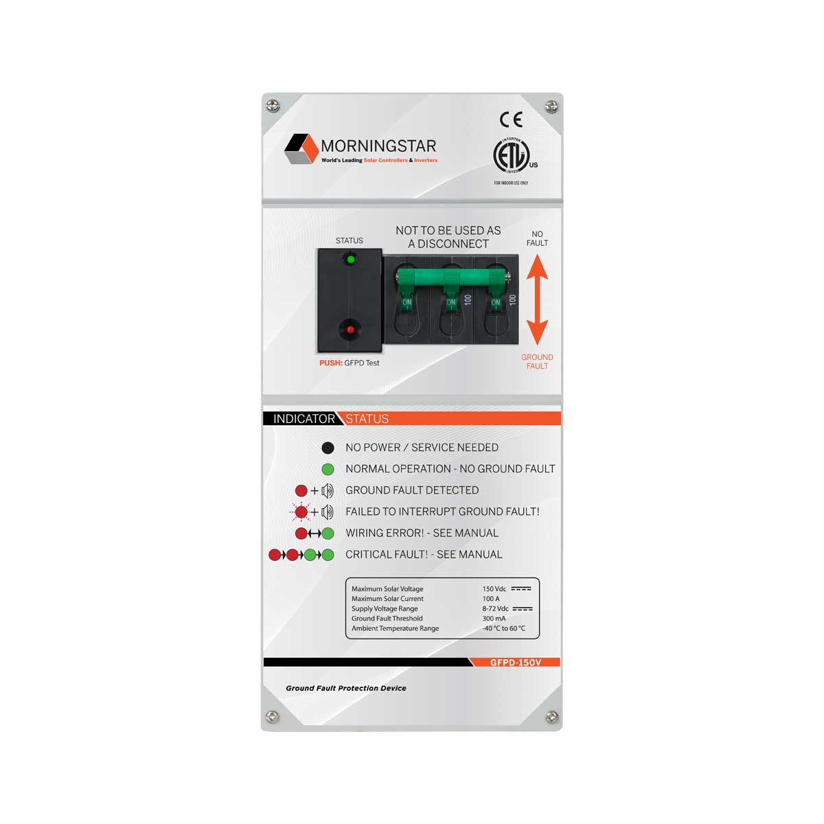
Here is an example of a PV GFP device that uses a Hall Effect Sensor:

 
Transformerless GT PV inverters have ungrounded PV arrays.
SMA pioneered this, and convinced the utilities and others it could be done safely (failures that end up driving PV DC into the grid would do really bad things to transformers.)

My Sunny Boy 10000TL-US calls for fuses in both PV+ and PV-
Normally, they run roughly centered around ground (so half the PV panels are positive biased in terms of PID, and half are biased negative.)
During power-up, the inverter runs a test where it pulls negative to ground, while testing for zero current.

If connected to 208V of a 120/208Y system, instead of array midpoint being at approximately ground (centered based on VAC positive peak and VAC negative peak), it is centered around the midpoint of 208V between to phases. Which is to say it swings 60 Vrms.

So no grounding there in the sense you would consider, but its voltage is defined based on grounded point of AC grid (PV is not galvanically isolated from grid.)

Most GT PV inverters are transformerless these days, of course. Perhaps some have high frequency galvanic isolation and could be grounded.
 
Here is an example of a PV GFP device that uses a Hall Effect Sensor:


Oh, right. PV is DC, so has to be hall effect.
The pictures someone posted looked like a transformer core. Might have actually been a core with a gap, and hall effect sensor in it.

(I've been playing with teslameters recently, also magnetization and degaussing. DC magnetic field sensor.)


The "blow a 1A fuse" or trip circuit breaker has got to be the simplest PV GFCI approach. But it needs the PV to have an isolated drive circuit (which an all in one like MPP could have), not going to work for transformerless GT PV.
 
Transformerless GT PV inverters have ungrounded PV arrays.
SMA pioneered this, and convinced the utilities and others it could be done safely (failures that end up driving PV DC into the grid would do really bad things to transformers.)

My Sunny Boy 10000TL-US calls for fuses in both PV+ and PV-
Normally, they run roughly centered around ground (so half the PV panels are positive biased in terms of PID, and half are biased negative.)
During power-up, the inverter runs a test where it pulls negative to ground, while testing for zero current.

If connected to 208V of a 120/208Y system, instead of array midpoint being at approximately ground (centered based on VAC positive peak and VAC negative peak), it is centered around the midpoint of 208V between to phases. Which is to say it swings 60 Vrms.

So no grounding there in the sense you would consider, but its voltage is defined based on grounded point of AC grid (PV is not galvanically isolated from grid.)

Most GT PV inverters are transformerless these days, of course. Perhaps some have high frequency galvanic isolation and could be grounded.
I could be wrong, but I don't think that is how the Growatt and MPP hybreds are set up. However.... there may be a thread in there that somehow excuses the Growat or MPP inverter's PV circuits from requiring grounding.
 
I could be wrong, but I don't think that is how the Growatt and MPP hybreds are set up. However.... there may be a thread in there that somehow excuses the Growat or MPP inverter's PV circuits from requiring grounding.

Probably not. Likely high frequency inverter (AC isolated from battery with high frequency transformer.) Does PV convert down to battery voltage? Often, that would be buck, with negative side to battery negative, so I don't know why they say not to ground (unless GFCI built in). Could be isolated converter, in which case GFCI fuse is possible. If not isolated, Hall effect seems like the way to do it.
 
Here is my resistance test of my MPP Solar 1012LV (Batteries not connected to the SCC): Notes, my probe leads' resistance is 0.50 Ohms.
PV (-) terminal of the SCC & Batt (-) terminal of the SCC = 0.50 Ohms.
PV (-) terminal of the SCC & Chassis = Around 500K Ohms.
Batt (-) terminal of the SCC & Chassis = around 350K Ohms.
Interesting. That implies the PV- and Batt- are tied together. This is common for many stand-alone MPPT chargers so it is not a surprise from that point of view. However, if that is the case, I don't understand the manual's warnings about not grounding the PV circuit.

Overall though, that is good news. That means if the battery negative is grounded, so is the PV- and that means that at least for the 1012LV, you can meet the requirement of grounding DC circuits that are over 60 V

However, @timselectric reported the Growatt SPF-5000-ES does NOT have continuity between PV- and Bat- so maybe my assumption that all the GW are the same is flawed.
 

diy solar

diy solar
Back
Top