timeforagorism
New Member
- Joined
- Oct 4, 2020
- Messages
- 8
The plot thickens! Thanks for all the updates everyone.


That would be great to see. The whole stud/base assembly being screwed in before welding would inspire more confidence in the connection.The supplier that I have that deals in a LOT of cells with studs, says they have a specially designed "screw pin" for adding the studs to the cells.
My understanding is that this "screw pin" has a screw coming out of the opposite side from where the stud is. It is screwed down into the threaded hole of the M6 poll and then laser welded.
I will try to confirm that 100% tonight and also see I can get a picture of said "screw pin" to be sure.
I think so too......but at this point that is my interpretation of what I was told and with the language barrier.......a picture to be sure is almost a must.That would be great to see. The whole stud/base assembly being screwed in before welding would inspire more confidence in the connection.
Could you also confirm if the whole assembly is aluminum? Thanks.I think so too......but at this point that is my interpretation of what I was told and with the language barrier.......a picture to be sure is almost a must.
In the example stud I posted earlier (with the round smaller raised pedestal, assuming M6 stud) I calculated the mating surface area to be ~19 sq. mm which would be equivalent in area to ~4.5 AWG. I don't know if a direct comparison to that size wire would be applicable. Maybe someone with more knowledge can figure out a safe amp rating for that area.I assume the concern is there won't be enough surface area when pulling large loads? If someone was going to run these at like 100 amp max would your concerns be less?
I would tend to agree with the square base but from what I am told they are almost all going to the round one. That could be wrong though. I guess we will see as the 2021 stock starts coming on the marketIn the example stud I posted earlier (with the round smaller raised pedestal, assuming M6 stud) I calculated the mating surface area to be ~19 sq. mm which would be equivalent in area to ~4.5 AWG. I don't know if a direct comparison to that size wire would be applicable. Maybe someone with more knowledge can figure out a safe amp rating for that area.
Regardless, it seems the square base that AussieSim posted would certainly be preferable.
I'm not sure if I would trust them too much, might just be a case of "if that gets your money, we'll do it ".Yeah, I am not experienced at all in the area of laser welding. And I don't know if the reduced surface area for mounting busbars or lugs will matter regarding current carrying capacity, although it is reduced quite a bit on account of the type of base they are using. I do think people need to be aware of this. Personally I don't know which way I would go. I guess we have to trust the suppliers know what they are doing. I know how difficult it can be to communicate with them due to the back and forth translations. Everyone needs to make their own decisions deciding on studs or screws.
That is one of the advantages of buying in a way that gives you enough buying power, that losing you as a customer is not worth what they would make on any individual order. Not to say that it could not still happen, just less likely.I'm not sure if I would trust them too much, might just be a case of "if that gets your money, we'll do it ".
Honestly I am leery trusting all of the suppliers and I could have been careful about my wording. But I believe the reputable suppliers want to keep their reputation and are not going to send out cells with defective welding.I'm not sure if I would trust them too much, might just be a case of "if that gets your money, we'll do it ".
Honestly I am leery trusting all of the suppliers and I could have been careful about my wording. But I believe the reputable suppliers want to keep their reputation and are not going to send out cells with defective welding.
I don't believe laser welding is the problem here. The problem for some may be the current carrying capacity of a welded stud with flange and pedestal vs a tapped terminal due to the reduced surface area of the welded stud.
I am very interested to see the actual part they are using. The part just lays on top of the terminal without any pressure when it is welded according to the video fission posted. Just laying there it would not be very good at carrying current. Agree so far? So then we can get into the current carrying capacity of the weld. There is no welding rod used. So how far into the terminal, and under the surface of the cells terminal, does the weld go? From the little I have read about laser welding the weld itself is very strong but thin.
Like I said I am no expert on this and here I go over thinking things. And I know laser welding is becoming more popular attaching "things" to the cells terminal. I just want to know what is the current capacity of the stud? We already know the "standard" single busbar shipped with cells, screwed or bolted down to the cells terminal can carry a lot of current. How much current can these laser welded studs carry?
For me laser welding is an interesting topic since I was in the laser hobby years ago. I used to buy DVD burners just so I could harvest the burner diode and make lasers out of them....lol. It was fun and did required eye protection. Always been fascinated by all types of lasers.
Well, I was right and then got clarification and ended up wrong after that LOL.
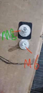
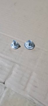
The cells my supplier is putting stud on come without any threaded hole at all. Just a flat blank surface.
Then they weld a stud on much like the one in the video. Although the M8 stud appears to have a chance of providing more surface area from what I can see. The M6 base is same as the cell surface area, and M8 is a little bigger than the cell.
It's an aluminum alloy base and alloy steel screw pin with aluminum as a part of that alloy. (so the threaded part is an alloy steal).
Yeah but here has to be a base because the base is providing support for the stud.It's a pity there is a step at the base of the stud, as that will be the only point of contact to the lug/busbar.
Thanks for doing the research. From the looks of it, I will stick with the M6 holes and possibly stripped threads until someone receives and confirms that the studs provide enough contact area for 280 amps.Well, I was right and then got clarification and ended up wrong after that LOL.
The cells my supplier is putting stud on come without any threaded hole at all. Just a flat blank surface.
Then they weld a stud on much like the one in the video. Although the M8 stud appears to have a chance of providing more surface area from what I can see. The M6 base is same as the cell surface area, and M8 is a little bigger than the cell.
It's an aluminum alloy base and alloy steel screw pin with aluminum as a part of that alloy. (so the threaded part is an alloy steal).

We don't know what the difference is. We do know a busbar torqued at 4.5nm or so works great. Look at all the forum members that have been doing it the traditional way (busbars and screws or studs) without any issues.Some concerns with these welded studs, illustrated.
-How good of a connection between the stud assembly and the battery post is this versus a torqued connection? Will this lack of torquing lead to increased heat/reduced amp capacity?
Yes there is. It's called silver conductive grease. It's expensive and isn't needed. Will Prowse recently tested four 272ah Lishen cells at full 1C rates and the busbars only got warm. And he was using single busbars.-There is probably no conductive compound/grease to increase the quality of connection and inhibit corrosion.
Isn't that what we have been implying? If I was buying cells I would go the traditional way and use busbars. If someone can test a cell with a laser mounted stud at full C rates and confirm the welded stud is capable of handling the current then I might be singing a different tune.-Reduced surface area on stud pedestal, possible reduced capacity versus connecting directly to the post. This does not seem to be a concern on the square stud assemblies.
I ordered 16 272's a few weeks ago and I might have opted for the studs if the option was available at the time. The max continuous discharge/charge I expect to see is only ~65A, so I'd expect the welded studs would be good for that. My biggest concern with the m6 threaded studs and bus bars is how well they will hold up in a high vibration environment (camper van). That's an awful small stud with a nut that can't really be torqued down too hard. I hope it all stays tight for the long haul. I'm building some enclosures to clamp the cells and will probably mount using some rubber bushings, but there is only so much that can be done to minimize vibration in a vehicle.Isn't that what we have been implying? If I was buying cells I would go the traditional way and use busbars. If someone can test a cell with a laser mounted stud at full C rates and confirm the welded stud is capable of handling the current then I might be singing a different tune.
Just to be clear, this diagram is of a welded stud assembly. I was just summing up the concerns people have voiced on them in an easy to understand diagram. Standard busbars with a stud screwed into post is obviously preferable unless you are willing to take the chance. As for the grease, do you know if the manufacturers are applying it beneath the welded stud? I know it exists and that it is used on batteries.We don't know what the difference is. We do know a busbar torqued at 4.5nm or so works great. Look at all the forum members that have been doing it the traditional way (busbars and screws or studs) without any issues.
It is recommended to use grub screws with a thread locker. And to sand the cells terminals with 600 grit or finer sand paper. Also the mounting holes in the busbars that come with the cells are stamped leaving a burr on one side. That needs to be addressed as well.
Yes there is. It's called silver conductive grease. It's expensive and isn't needed. Will Prowse recently tested four 272ah Lishen cells at full 1C rates and the busbars only got warm. And he was using single busbars.
Isn't that what we have been implying? If I was buying cells I would go the traditional way and use busbars. If someone can test a cell with a laser mounted stud at full C rates and confirm the welded stud is capable of handling the current then I might be singing a different tune.
I don't know. Perhaps @Michael B Caro could ask his supplier. But I doubt it.As for the grease, do you know if the manufacturers are applying it beneath the welded stud?
You are welcome. One of my cells looked like the attached photo. It looks much better nowThanks for the tip on sanding terminals/cleaning up stamped busbars
")
My cells will remain stationary but I understand your concerns. There are people much more knowledgeable than I am using these cells in mobile environments. One idea would be to use NORD-LOCK washers. I don't know anything about them except them being mentioned on the forum. As you said clamping the cells is a must.I ordered 16 272's a few weeks ago and I might have opted for the studs if the option was available at the time. The max continuous discharge/charge I expect to see is only ~65A, so I'd expect the welded studs would be good for that. My biggest concern with the m6 threaded studs and bus bars is how well they will hold up in a high vibration environment (camper van). That's an awful small stud with a nut that can't really be torqued down too hard. I hope it all stays tight for the long haul. I'm building some enclosures to clamp the cells and will probably mount using some rubber bushings, but there is only so much that can be done to minimize vibration in a vehicle.
Thanks. On the lishens, there is reference to clamping in the spec sheet similar to the eve cells. I did see the reports on the positive case and they should be well isolated and my battery enclosures will surround the cells with hdpe sheet, so hopefully covered there.My cells will remain stationary but I understand your concerns. There are people much more knowledgeable than I am using these cells in mobile environments. One idea would be to use NORD-LOCK washers. I don't know anything about them except them being mentioned on the forum. As you said clamping the cells is a must.
There have been reports of positive voltage on the cell casing. I would suggest putting some type of insulation between the cells to make sure they stay isolated from each other. Cell terminal stress has also been discussed. Using braided busbars or battery cables will alleviate that. EVE cells expand and contract with SOC. I don't know if this is a concern with Lishens. There are several threads that discuss the amount of clamping force to extend the life cycle of EVE cells. It would be nice to know what Lishen recommends.
I can askI don't know. Perhaps @Michael B Caro could ask his supplier. But I doubt it.