diy solar

diy solar

Chargery BMS, DCC (Solid State Contactor) thread.

CHARGERY
Product Code: BMS8P-300 V4.05
Availability: In Stock
$189.90
... Has anyone been using the newer Chargery BMS8P ... enough to give us a report ? https://www.chargerystore.com/index.php?route=product/product&path=20_26&product_id=85 :+) ... notice web info says: ... and wondering about this:

Chargery says: "Balance current:1.2A per cell, Continuously balancing."
.... is that Active Balance ability really "Continuous"? ... or is this a chinese - english translation mistake in print?

I would want to be able to adjust when Active Balancing turns on, and off; like for choosing ON for >3.35v or 3.4v cell voltage., and OFF <3.35v or <3.4v. ... I have been thinking that way since taking in some recent info of youtube lesson clips that show how active balancing at lower cell voltages "can" ... unbalance your cells; with that possibly showing up when cells get back up to the top charge levels.

I think the Chargery BMS P versions and older BMS T versions use the same firmware updates ??? which in my BMS8Ts have adjustable Balance parameters including off and ons for charge, discharge, and storage, and cell voltage starts.

Who has tried this newer version of Chargery BMSP , and done some test driving ??? What do you think of it?
Might work awesome or not ?
 
Last edited:
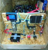
BTW, My Chargery Bank, 24V 8S packs with BMS8T-300 & DCC-300.
lfp-4-pack-bank-dec-2020-interim-jpg.30544
Yo Steve; Awesome Looking LiFePO4 Battery Bank. Question: With a BMS for each set of battery cells in those boxes; Do you have the BMS triggers wired to disconnect at One Main Battery Relay? or at do your BMS triggers Disconnect at Separate Independent Relays ... as in one for each box of batteries??? (at closer examine of picture, it looks like one of those newer Chargery DDC Solid State Contactors for each BMS) ... I am looking at my options for wiring up two 24v 280Ah 8 cell sets together in parallel with two separate Chargery BMS8Ts to double my Ahs; and can see option to go either way (as in One Main Battery Connnect & Disconnect Relay, or Two such Relays) ....with the extra 500Kilovoc Relays and SSRs I have to work with. ... I have thought of pros and cons for both ways. I could see two relays to disconnect battery at each 8 cell line Pros as being ... when one set was released, it would leave the solar all in ones networked together (MPP LV2424s) I have still working. Cons might be the voltage difference when a triggered off relay automatically reconnected, or the potential for off and on cycles when I was not there to monitor and correct a BMS trigger situation. I Am Open to Feedback and/or Opinions from anyone here on this forum, before I rewire my solar wall.
 
Last edited:
Yo Steve; Awesome Looking LiFePO4 Battery Bank. Question: With a BMS for each set of battery cells in those boxes; Do you have the BMS triggers wired to disconnect at One Main Battery Relay? or at do your BMS triggers Disconnect at Separate Independent Relays ... as in one for each box of batteries??? (at closer examine of picture, it looks like one of those newer Chargery DDC Solid State Contactors for each BMS) ... I am looking at my options for wiring up two 24v 280Ah 8 cell sets together in parallel with two separate Chargery BMS8Ts to double my Ahs; and can see option to go either way (as in One Main Battery Connnect & Disconnect Relay, or Two such Relays) ....with the extra 500Kilovoc Relays and SSRs I have to work with. ... I have thought of pros and cons for both ways. I could see two relays to disconnect battery at each 8 cell line Pros as being ... when one set was released, it would leave the solar all in ones networked together (MPP LV2424s) I have still working. Cons might be the voltage difference when a triggered off relay automatically reconnected, or the potential for off and on cycles when I was not there to monitor and correct a BMS trigger situation. I Am Open to Feedback and/or Opinions from anyone here on this forum, before I rewire my solar wall.
Hi Capt Bill,

Based on Steve_S's design and other info on the forum, I went with separate 16S 280AH battery packs. Each has its own Chargery BMS-16T, DCC-300, Heltec 5A active balancer and 250A class T fuse. I think individual strings might be a little safer than having two cells in parallel without a fuse between them but it does require additional BMSs, etc.

Each pack was top balanced, charging most of the way with all the cells in series (48V) to reduce the time required. When the difference in cell voltages got to about 150mV, I reduced the charging current and then used a bench supply to tweak each cell to the final value of 3.65V. During that phase, I disconnected the pack from everything but the bench supply so I didn't have to disconnect the cells from one another.

After resting overnight the packs were within 100-200mV of each other. The wiring was connected to the inverter and MPPTs and the packs were switched on one at a time with the DCC-300s. The voltage was close enough that there were no large current spikes. The packs seem to share charge and discharge current fairly evenly. They don't track exactly, probably because I sorted the multiple cells into capacity from high to low and made packs of similar capacity. I might mix up the capacities in each pack if I did it again and let the balancer try to equalize charge within each pack. There might also be some slight differences in wiring since I finished the first two packs with existing cables while waiting for more parts to arrive.

Once the system is up and running, the DCC-300 should never need to disconnect unless there is a fault (like my tablesaw incident). The MPPT and inverter/charger bulk voltage should be less than the BMS high voltage disconnect. Currently I charge to 54.8V (3.425V per cell) but may tweak this a little in the future. My generator auto starts at 50.6V after 30 seconds (3.16V per cell) which only happens in mid-winter. In my system, the BMS should only disconnect under a fault condition like too great a cell voltage difference, pack over or under voltage, over current or temperature limit. The packs do not cycle on / off individually or at all from what I've observed.

When completed, all the battery packs will be paralleled onto a bus bar which connects to the inverter and MPPTs. The final pack design looks like this:
BatteryPack16S.jpg
They are sitting on individual dollies or can be stacked two high on a single dolly.

The packs each have their own shunt and then all the negative cables are combined and run through a Schneider battery monitor shunt. The Schneider battery monitor appears to be more accurate than the Chargery BMS. The Chargery BMS will record less than the actual current since anything below 0.5A = 0A. This is compounded by having parallel packs. For example with two packs, when the Schneider says 0.5A, the two Chargery shunts will record zero since with two in parallel they only see 0.25A each. This happens a lot when the system goes into float during the day. I'm not completely comfortable with the fuel gauge measurements of the Chargery or Schneider hardware, but overall, it does not seem to be a big deal since my system currently decides when to charge or stop charging based on voltage. If you take that approach, Steve_S has some info on calibrating voltages across devices which should be considered to make sure your batteries see the voltages you are expecting.
 
The packs shown are 24V 8S Block Format. BMS8T-300 with 300A DCC each.
Each also has a QNBBM-8S Active Balancer.
I cannot recommend paralleling cells unless they are well matched.

As for the Chargery "Fuel Guage" SOC it's not too good. The Midnite Solar WizBangJr Monitor is actually not very far off for the whole bank. I set the chargery's to disconnect at set voltage and they do, but I disabled the disconnect based on SOC and that never worked right.

In any case, I am in process of making my final mods to my whole system, that includes changing all the BMS' to JK's with 2A Active Balancing and normalizing / simplifying everything. With 3x 280AH & 2x 175AH its like herding feral cats... I'm even doing my Utility packs over to same BMS etc...
 
Hello community,

I recently installed a chagery system(BMS 16, 600A shunt, 2 DCC (600Amp for discharge and 300Amp for charge)) for my DIY LIion Battery pack, which is installed on my golf cart. Everything seemed to be fine until all the sudden the discharge DCC started acting up. Both LEDs on the DCC are flashing as well as the discharge LED on the ISO Board. If I disconnect the DCC control cables or turn the DCC off the LED on the ISO Baord stays solid. It seems like that the DCC is stuck closed and only works in one direction.

Does anybody know how to fix this and what have caused this behavio?

I have not took the DCC apart since I am awaiting an email response from Jason.

Here is a short video:
 
Last edited:
Hello community,

I recently installed a chagery system(BMS 16, 600A shunt, 2 DCC (600Amp for discharge and 300Amp for charge)) for my DIY LIion Battery pack, which is installed on my golf cart. Everything seemed to be fine until all the sudden the discharge DCC started acting up. Both LEDs on the DCC are flashing as well as the discharge LED on the ISO Board. If I disconnect the DCC control cables or turn the DCC off the LED on the ISO Baord stays solid. It seems like that the DCC is stuck closed and only works in one direction.

Does anybody know how to fix this and what have caused this behavio?

I have not took the DCC apart since I am awaiting an email response from Jason.

Here is a short video:

Hi @Joe85,

If I recall, that flashing LED scenario is what happened when I blew up a DCC-300 (see page 24 of this thread for details and more photos). What was the golf cart doing when this happened? If you were trying to accelerate under a heavy load (maybe floored it from a stop going up a steep hill?) the battery current would be quite high. If you tripped the overcurrent limit and the DCC-600 tried to disconnect the batteries that might fry it. Same if the battery voltage sagged too low and it tripped on under voltage. It sounds like it's fried and will need to be replaced or repaired.

Check the overcurrent limit setting in the BMS. If it is set too low for the DCC-600, that could have caused it to disconnect. In that case, you would have to power cycle the BMS to get it to come back on. If it disconnected due to low voltage, you would not need to power cycle the BMS to see it try and turn on the DCC. This low voltage disconnect scenario seems more likely to me.

Obligatory Disclaimer:
Keep in mind that there is a lot of power stored in your batteries. Unless you have the appropriate level of skill and knowledge don't try this at home! You could be burned, blinded or die.

Pretty sure an over current disconnect under an extremely heavy load is what happened to mine. There were obvious signs of damage around the power transistors. You should be able to see this kind of damage by removing the top half of the case and looking at the edge of the PCB under the heatsink.

I was able to disassemble the unit I fried and have ordered some replacement MOSFETs. The trick is to clip all the MOSFET leads right at the PCB and remove the whole MOSFET heatsink assembly. Be careful not to break the small areas of glue that are holding the two heatsinks spaced apart. Then desolder the leads remaining in the PCB and clean out the holes to insert the new MOSFET leads. This assumes you will replace all 8 MOSTFETs on the DCC-300 (there are probably more on the DCC-600). The MOSFETs have to be attached to the heatsinks before they are soldered to the PCB.

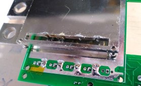
You can probably remove the MOSFETs without removing the large slotted copper plate on the back of the PCB but I didn't realize that at first. If not, clip the MOSFET leads that are soldered to the copper plate on the back of the PCB. Next, slip something thin between the PCB and the copper plate at one corner and heat the copper pads on the PCB that are touching the plate one at a time. The copper plate on mine was just barely soldered to the PCB traces where the leads came up and attached to the copper plate. With a little tension, heating the traces allowed the plate to pop loose. Be cautious and start at one corner. Here's what it looks like after I removed the plate and placed it upside down on the PCB so you can see the soldered areas.

DCC300_CopperPlate.jpg

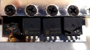
The DCC-300 uses 8 MOSFETs from Oriental Semiconductor.
DCC300_MOSFETs.jpg
They are N-channel, 60V, 200A (600A pulse) with RDSon=2.5mOhms. Part number SFS06R02P. The datasheet is here:


There was one seller of this part on AliExpress when I looked but due to counterfeit semiconductor concerns, I opted for a similar device from Digikey: IRFB3207PBF. The specs are not exactly the same, but probably close enough. I'll find out in another week or two.
 
Only 4 MOSFETs per side at 2.3 mOhm each and 300 A total current? that's a lot of losses (almost 104 W) and not much surge capability :rolleyes:

I'd recommend to find ones with a lower Rdson (and only from a top tier manufacturer) if you want to improve reliability and losses ;)

Edit: quick search retrieved three under 2 mOhm with same or better specs otherwise and in stock:

1.8 mOhm https://www.mouser.fr/ProductDetail/Toshiba/TK100E06N1S1X?qs=VMlqFFbv3sRy7Xuh0p8bmw==
1.65 mOhm https://www.mouser.fr/ProductDetail/onsemi-Fairchild/FDP020N06B-F102?qs=0lQeLiL1qya8730qZbQYRA==
1.6 mOhm https://www.mouser.fr/ProductDetail/Texas-Instruments/CSD18536KCS?qs=UfUFg/kmHHE2X%2BOrReBFew==

The last ones are pretty expensive compared to the 1.8 mOhm one for not much more improvement so I think the 1.8 mOhm one is the ideal middle ground at 2.18 €/unit in /10 quantity.

That would bring the dissipated power down to 81 W, reduce the Tj and so improve the lifespan and reliability quite a lot.
 
Last edited:
Only 4 MOSFETs per side at 2.3 mOhm each and 300 A total current? that's a lot of losses (almost 104 W) and not much surge capability :rolleyes:

I'd recommend to find ones with a lower Rdson (and only from a top tier manufacturer) if you want to improve reliability and losses ;)
...
That would bring the dissipated power down to 81 W, reduce the Tj and so improve the lifespan and reliability quite a lot.
Great comments. I looked around at Digikey and Mouser but didn't look beyond about 250A so missed the parts you found at Mouser. Thanks for taking time to add those options. The Infineon part I selected has a higher Rdson so I'll probably order one of those you found to reduce the losses and keep the Rdson in the 4 DCC-300s more closely matched to balance the charging and discharging across the packs.

100W loss on 54V * 300A = 16.2kW in the DCC-300 is about 0.625%. The temperature rise is a bigger concern if running a DCC-300 at 300A continuously. In my system I have 4 parallel 48V packs, each with a DCC-300. The max charging current will be about 50A per pack unless one trips off line. The load current will be about 12kW max or about 225A at 54V, again, about 50A per pack. The typical system load will be 500W - 1kW so I'm not too worried about the junction temperatures. I've never seen the fans run even with just 2 packs on line and charging at 70A per pack.
 
I recently installed a chagery system(BMS 16, 600A shunt, 2 DCC (600Amp for discharge and 300Amp for charge)) for my DIY LIion Battery pack, which is installed on my golf cart. Everything seemed to be fine until all the sudden the discharge DCC started acting up. Both LEDs on the DCC are flashing as well as the discharge LED on the ISO Board. If I disconnect the DCC control cables or turn the DCC off the LED on the ISO Baord stays solid. It seems like that the DCC is stuck closed and only works in one direction.

Does anybody know how to fix this and what have caused this behavio?

I have not took the DCC apart since I am awaiting an email response from Jason.

Here is a short video:
... for a quick alternative to play with while figuring out your damaged DCC-600, you might consider a Kilovac EN200 Relay rated for 500 amps and up to 900vdc (with those economizer on relay coil for low 0.03amp holding current (after 1.3A inrush to clamp relay) ... just saw some used and new open box ones on eBay for about $40. ... Or ... Here's a brand new one I just ordered to have as a backup for a couple of 300amp fused 24v 280Ah battery bank disconnects ... at a super econ price, ...@ slower delivery, or pay extra for faster shipment/at still way worth price: https://www.aliexpress.com/item/1005003965292904.html?spm=a2g0o.order_detail.0.0.739ef19cvckp20

... I now look at the four digit manufacture dates at bottom of those Kilovac Relay lables/ w first 2 digits representing year of manufacture. Had a couple of used 2008 era and one 2014 go sour on my live n learn experiment curves. I now use SSRs on my two Chargery BMS8T's @ my Charge and DisCharge Triggers ... to route power from a separate small 24vdc lead acid battery to power my relays (including some Solar IN Relays that click off at Charge side Triggers). I also power the ext power plugs of my 2 BMSs with same separate small 24vdc battery (floated at28v). ... I like how this results in low amp loads on all my BMS triggers, PLUS my 2 BMSs are functioning when a Discharge Trigger(s) fully Disconnect one or both of my 24vdc battery banks, and there is absolutely no idle draws on when my BMS fully disconnects my LifePO4s. ... Food for Thought on Options :+)
 
Last edited:
... for a quick alternative to play with while figuring out your damaged DCC-600, you might consider a Kilovac EN200 Relay rated for 500 amps and up to 900vdc (with those economizer on relay coil for low 0.03amp holding current (after 1.3A inrush to clamp relay) ... just saw some used and new open box ones on eBay for about $40. ... Or ... Here's a brand new one I just ordered to have as a backup for a couple of 300amp fused 24v 280Ah battery bank disconnects ... at a super econ price, ...@ slower delivery, or pay extra for faster shipment/at still way worth price: https://www.aliexpress.com/item/1005003965292904.html?spm=a2g0o.order_detail.0.0.739ef19cvckp20

... I now look at the four digit manufacture dates at bottom of those Kilovac Relay lables/ w first 2 digits representing year of manufacture. Had a couple of used 2008 era and one 2014 go sour on my live n learn experiment curves. I now use SSRs on my two Chargery BMS8T's @ my Charge and DisCharge Triggers ... to route power from a separate small 24vdc lead acid battery to power my relays (including some Solar IN Relays that click off at Charge side Triggers). I also power the ext power plugs of my 2 BMSs with same separate small 24vdc battery (floated at28v). ... I like how this results in low amp loads on all my BMS triggers, PLUS my 2 BMSs are functioning when a Discharge Trigger(s) fully Disconnect one or both of my 24vdc battery banks, and I know there is absolutely no idle draws on my BMS triggered disconnects of my LifePO4s. ... Food for Though on Options :+)
Thanks for giving me those alternIves ?
 
Hi @Joe85,

If I recall, that flashing LED scenario is what happened when I blew up a DCC-300 (see page 24 of this thread for details and more photos). What was the golf cart doing when this happened? If you were trying to accelerate under a heavy load (maybe floored it from a stop going up a steep hill?) the battery current would be quite high. If you tripped the overcurrent limit and the DCC-600 tried to disconnect the batteries that might fry it. Same if the battery voltage sagged too low and it tripped on under voltage. It sounds like it's fried and will need to be replaced or repaired.

Check the overcurrent limit setting in the BMS. If it is set too low for the DCC-600, that could have caused it to disconnect. In that case, you would have to power cycle the BMS to get it to come back on. If it disconnected due to low voltage, you would not need to power cycle the BMS to see it try and turn on the DCC. This low voltage disconnect scenario seems more likely to me.

Obligatory Disclaimer:
Keep in mind that there is a lot of power stored in your batteries. Unless you have the appropriate level of skill and knowledge don't try this at home! You could be burned, blinded or die.

Pretty sure an over current disconnect under an extremely heavy load is what happened to mine. There were obvious signs of damage around the power transistors. You should be able to see this kind of damage by removing the top half of the case and looking at the edge of the PCB under the heatsink.

I was able to disassemble the unit I fried and have ordered some replacement MOSFETs. The trick is to clip all the MOSFET leads right at the PCB and remove the whole MOSFET heatsink assembly. Be careful not to break the small areas of glue that are holding the two heatsinks spaced apart. Then desolder the leads remaining in the PCB and clean out the holes to insert the new MOSFET leads. This assumes you will replace all 8 MOSTFETs on the DCC-300 (there are probably more on the DCC-600). The MOSFETs have to be attached to the heatsinks before they are soldered to the PCB.

You can probably remove the MOSFETs without removing the large slotted copper plate on the back of the PCB but I didn't realize that at first. If not, clip the MOSFET leads that are soldered to the copper plate on the back of the PCB. Next, slip something thin between the PCB and the copper plate at one corner and heat the copper pads on the PCB that are touching the plate one at a time. The copper plate on mine was just barely soldered to the PCB traces where the leads came up and attached to the copper plate. With a little tension, heating the traces allowed the plate to pop loose. Be cautious and start at one corner. Here's what it looks like after I removed the plate and placed it upside down on the PCB so you can see the soldered areas.

View attachment 88937

The DCC-300 uses 8 MOSFETs from Oriental Semiconductor.
View attachment 88938
They are N-channel, 60V, 200A (600A pulse) with RDSon=2.5mOhms. Part number SFS06R02P. The datasheet is here:


There was one seller of this part on AliExpress when I looked but due to counterfeit semiconductor concerns, I opted for a similar device from Digikey: IRFB3207PBF. The specs are not exactly the same, but probably close enough. I'll find out in another week or two.
Thanks for all that info :)
The golf cart is hoisted up in my garage. When this happened I had the 12V step down converter turned on which powers a few LEDs. So not much current all. Also the speed controller was turned on but was idling. I dont really recall exactly what I did right before this happened, but I think I power cycled the DCC with the manual switch. I am just surprised that this would destroy the DCC. ?

Jason hasn’t responded yet, but I will definitely disassemble the DCC to maybe see what is broken
 
Hi @Joe85,
That seems pretty odd. I can't imagine why it would fail from a power cycle with just a small load. Have you checked the voltages with a meter? Check both sides of the DCC to negative and see what happens when you switch it on. Could the problem be something other than the DCC? Any fuses blown? Loose connections? A quick hand drawn sketch of your system might be helpful.
The DCC is stuck close all the time regardless if the switch is on or off. Also the DCC works only in one direction. I can Spinn the wheels of the golf cart but cannot regenerate braking energy back to the battery.
i am currently not home, once I am back home I can post a System diagram
 
The DCC is stuck close all the time regardless if the switch is on or off. Also the DCC works only in one direction.
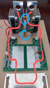
More and more curious. I have the common port version where charge and discharge are combined but I suspect the separate port unit you have is similar inside. Under a heavy load, mine failed open. I wonder if the MOSFETs failed or if maybe something else shorted. There are some close spaces inside. Could a piece of wire or metal have fallen into the ventilation slots? Or maybe the terminals sticking out got twisted? The large heatsink is two pieces, one connected to each terminal on the separate port unit. You can see the current flow drawn in red on this photo. There are two blobs of glue that hold the two heatsinks apart circled in blue. If something gets between the heatsinks the DCC would be shorted on. It seems unlikely that the terminals could be twisted sideways enough to short the heatsinks together even if the glue came loose. The MOSFET leads would have to bend quite a bit for the heatsinks to touch, although without the glue there is nothing else but the leads to hold them apart. There is a sheet of insulating material between the heatsinks and the top of the case. Same under the PCB below the big copper plate.

ChargeryDCC300_CurrentPath.jpg
At least two MOSFETs would have to short to make the device stay on since there are 4 in parallel in series with 4 more in parallel on the common port DCC-300. Unless something else failed in the DCC circuitry that controls the MOSFETs.

What happens if you unplug the ISO board from the DCC? Will the wheels still spin? It seems likely if they still spin when the switch is off. Also, when the wheels spin, is there enough torque to move the golf cart?

Hopefully Jason will reply since this sounds like it might be covered under the 12 month warranty. I totally fried mine so I wouldn't ask him to cover it but it sounds like you didn't do anything out of the ordinary.
 
Chargery DCC is simply a piece of sh*t according to my experience. I now have five failed DCCs:
1. DCC300. FAILED CLOSED
2. DCC300. FAILED CLOSED
3. DCC300. FAILED CLOSED
4. DCC300. FAILED CLOSED
5. DCC100. FAILED CLOSED
None of these was used between battery and inverter and none of them lasted up to six months. Jason also never responded to my questions. I am not using Gigavac GX14.
 
Do the DCC run excessively hot?
I have a 560ah 12v 2P4S set up with BMS 8T and separate port 300a/100a(charge). The maximum load I subject it to is circa 190a where there is a significant drop across the DCC 300a which increases as the DCC heats up quickly dropping the output to below 12 volts. The voltage at the cells remains above 12.6v throughout. At low current things are seemingly normal. All connections have been remade and I’m happy that they are good. Has anyone experienced similar or do I simply have a bad DCC??
 
Chargery DCC is simply a piece of sh*t according to my experience. I now have five failed DCCs:
1. DCC300. FAILED CLOSED
2. DCC300. FAILED CLOSED
3. DCC300. FAILED CLOSED
4. DCC300. FAILED CLOSED
5. DCC100. FAILED CLOSED
None of these was used between battery and inverter and none of them lasted up to six months. Jason also never responded to my questions. I am not using Gigavac GX14.
I had 3 fail... the start surge got mine because their stupid soft start only works when you manually throw the swtich. softstart does not work when the unit is controlled on/off by the electrical interface. silly silly silly...
 
Chargery DCC is simply a piece of sh*t according to my experience. I now have five failed DCCs:
1. DCC300. FAILED CLOSED
2. DCC300. FAILED CLOSED
3. DCC300. FAILED CLOSED
4. DCC300. FAILED CLOSED
5. DCC100. FAILED CLOSED
None of these was used between battery and inverter and none of them lasted up to six months. Jason also never responded to my questions. I am not using Gigavac GX14.
Oh wait... you are the guy I shipped my units to!!! Hyvaa huomenta
 
onder
Chargery DCC is simply a piece of sh*t according to my experience. I now have five failed DCCs:
4. DCC300. FAILED CLOSED
5. DCC100. FAILED CLOSED
None of these was used between battery and inverter and none of them lasted up to six months.
I wonder what you used them for. ??? ... I had the smaller 100 amp ones fail w about 3 weeks of use on one of my 80vdc-30Amp PV Inputs to my LV2424 All in One as an OFF switch for BMS Charge Trigger). ... I theorized the MPP protocols going through one of those DCCs does something/ and not a good match mix, ... but no real proof that was the isse. (added later note: from info later in this thread, ... I see my PV In volts were above the DCC's specs. for max volts). I am using the Kilovac 500 amp relays for my battery off/on switches. ... last couple of new purchases on alxiexpress were < $40 vs sometimes $200 in USA. Ali shipping time was a ok zone too (< 2 weeks).
 
Last edited:
I wonder what you used them for. ???
They are used in the place of internal FETs or as a substitute for an external Contactor. As far as I know all EVs use Contactors because they can withstand the high amperage. FETs and Solid State Contactors unfortunately often fail closed as in the case of these DCCs. The Kilovac is a great Contactor.
 
Back
Top