diy solar

diy solar

Chargery BMS, DCC (Solid State Contactor) thread.

Looks like the terminal on the right in this chargery pic…

My “guess” would have been that it does not matter but following the official pic should be safe(st).

View attachment 70181
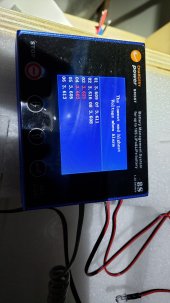
From my understanding it does not matter. I have read this somewhere and does not matter due to the nature of it being bidirectional. When BMS stops suppling power it cuts off power between the two terminal.

Answer one comment you had above The fix for terminals (Don't know what version) length not the width apart. Before the nut would be almost mm away from the metal plate of the DCC. They are now extended a good bit.

Not sure if Jason is interested in this as much anymore or he has became supper busy. The communication was pretty great with him for long while but lately nothing. This AM I have emailed him again in regards to my DCC issue. I think my issue is it being one of the very first few told it would work in separate port and not necessary designed with the changes, such as later on you had to specify if it's use was in common or separate port, Was mentioned this is due to cable supplied with them but seems like it is something internally with the DCC because of a comment above from Jason. He mentions it should have a label on it etc. Also little bit later on the ability to run it on the positive side but only with the ISO board. So I think this also compiles to the issues if with earlier version. My DCC also has some issue going on due to the fan running non-stop. The spec sheet clearly states when it comes on and I was no where close to that temperature and no load because it will not connect, stays disconnected. Only one red LED on but the status LED only flashes a millisecond when flipping the switch on back of the DCC.

My newer ordered this year (Specified separate port) DCC-100 for the charge side works just fine. I need my load one working and my goal to have this built, tested with months to spare now comes to an end as I need it in NOV. But the response from Jason has not been that great.
 
What is the difference between chargery bms16T and BMS16 v2.0? or can someone point me to the right thread? thank you
I think it would be more helpful to include your source in regards to the v2.0. Where did you see / read it and that will help answer your question instead of starting some rumer of such with just assumptions
 
Question that may or may not have been covered.

Are these units "fail on" or "fail off" designs?
I have had a number of SSRs over the years which we use on exactly one machine in our plant for a heating circuit that fail from time to time and when they do so they "fail on" which results in a very severe overheating condition.

"Fail off" ssrs are a thing, but I can never convince anyone to spend the extra coin for them when it comes time for me to replace another one.

Since I didn't look too far into the actual switching device here I'm just curious to know if this solves the one thing I'd really worry about with solid state.

Obviously failing in the "on" state would be detrimental and counter to the intent of the product.
From an HVAC perspective .... a heating circuit in a commercial environment is always designed to ... fail to heat. At least in a location where sub freezing temperatures can be expected.

A warm weather climate would be different.
 
From an HVAC perspective .... a heating circuit in a commercial environment is always designed to ... fail to heat. At least in a location where sub freezing temperatures can be expected.

A warm weather climate would be different.
Not if it's a manufacturering process that will shoot to 900f when it's not supposed to ever exceed 662f.

But the point here is a bms should fail off.
 
I don't use the DCC .... but it will act like a normally open relay.
 
I don't use the DCC .... but it will act like a normally open relay.
Will it though?

Because a standard SSR fails "closed", and thus in the "on" state.

Not that I'm saying it does or doesn't behave this way here just trying to find confirmation.
 
There are Chargery BMS## BMS', the originals with revisions.
Then there are the BMS##T which followed the above and now the BMS##P series is the latest.

Please refer to the Newer Chargery Site for info.
 
What is the difference between chargery bms16T and BMS16 v2.0? or can someone point me to the right thread? thank you
At a minimum, the v2.0 has an integral display while the T version has a separate display unit connected to the main unit by a coiled cord. Check out the manuals on the Support page for more details.
 
@Steve_S .... Do you have one of the "P" units yet?

Well .... maybe I got my hopes up too soon. I saw the P version listed in the update log, but don't see any manuals for them .... or see the product listed for sale.
 
Last edited:
Brands CHARGERY
Product Code: BMS8P-300 V4.05
Availability: In Stock
$189.90

He has a link to a Manual, but it's the one I did for the T Series and does not seem to be updated at this time from what I saw.
I don't have any P Series, I only just found out they were available by accident.
I also got a newer version of the DCC recently (for the 5th pack) and it is different / improved than the first versions Way Back When.
 
Thanks Steve ..... They need to make it easier to find. Maybe still in the release process.
 
Is the difference in resistance and voltage something to be concerned about ?
 

Attachments

  • 20211029_112333.jpg
    20211029_112333.jpg
    70.8 KB · Views: 20
  • 20211029_112853.jpg
    20211029_112853.jpg
    106.6 KB · Views: 20
Is the difference in resistance and voltage something to be concerned about ?
I would be far more concerned about charging cells over 3.6V every charge cycle if that is what you are doing.

Your cells look REALLY well behaved up at near max voltage. Keep doing what you are doing and buy lottery tickets.
 
Maybe I'm missing something?
This is the chargery thread so we should get a new thread with your SCC issues.
Or contact me in a message.

I would be looking at your Renogy SCC settings to change your charge profile.

Your BMS settings are mostly determined by your battery type, and narrowed a little for more conservative, potentially battery lifetime increasing charges.
 
I'm working on the SOC calibration as directed in the chargery manual.
What should I use as a cell voltage figure when calculating the WH and AH of my LFP batteries.
3.65v or less.
i.e. what is the recommended top state of charge for the cells?
 
There are Chargery BMS## BMS', the originals with revisions.
Then there are the BMS##T which followed the above and now the BMS##P series is the latest.

Please refer to the Newer Chargery Site for info.
Thanks Steve for the heads up on the new model. I've been waiting for this. Since there doesn't seem to be a user manual released yet, does anyone know if the P series has CAN Bus, and if so, any protocol information?
 
My Chargery 300 BMS is shutting off the batteries occasionally when I use my miter saw… no fuses are being switched, it just disconnects and I have to reboot the BMS, then it works again.

24v system, LFP 280a, 16 cells 2p8s configuration
 
My Chargery 300 BMS is shutting off the batteries occasionally when I use my miter saw… no fuses are being switched, it just disconnects and I have to reboot the BMS, then it works again.
You might check the "Over Discharge Current" setting. That seems like an error that might require a reset. Even if set to 300A, your miter saw will draw a very large start-up current and may trip it, especially with a long extension cord (slower to spin up to speed at lower voltage). A 24V system at 3.4V/cell is 27.2V. Multiplying that by 300A is 8.16kW which you may very briefly be exceeding.

During initial top balancing, I saw the DCC-300 disconnect based on exceeding the "Difference of Cell Voltage" limit but it automatically reconnected without needing to be reset. There is a list of possible disconnect triggers in the FAQ section on page 62 of the BMS16T manual but it doesn't say which require a reset.
 
Back
Top