tim0shel
Solar Enthusiast
- Joined
- Jan 27, 2020
- Messages
- 464
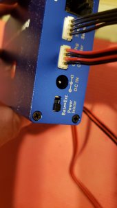
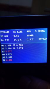
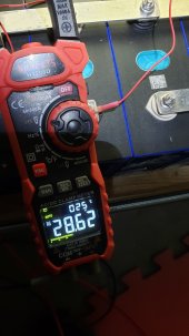
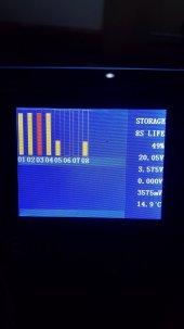
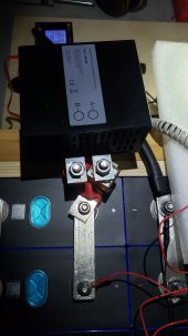
You're correct here the mosfet is turned off as the DCC300 is not coming on hence why the other light does not light up. Status light when flipping the switch comes of for less than a second and goes back off. Reason I though it was working was due to the load side working like some USB ports I was using. But this is Back Flowing from the DCC100.when DCC cut off charge or discharge, the voltage drop from input and output is caused by internal surge suppressing circuit, means mosfet is turned off, although the voltage is 12.82v on output, but the battery don't be charged or discharged. when the STATUS LED on, means mosfet is turned on, the voltage on input and output has not difference, battery can be charged or discharged.
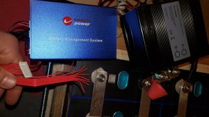
when internal temperature over 41 C, the fan will turn on, and powered by battery, the fan current is around 0.2A at 12V. when udner 38C, the fan will turned off.
Also the fan constantly runs, it does not shut off and the temp recently has been almost 63 F or 17.2 C .