diy solar

diy solar

Chargery BMS, DCC (Solid State Contactor) thread.

Testing my DCC's and charging the battery until I hit over charge protection I've noticed in my separate port configuration that both the charge and load DCC cut off. I do have an old original load DCC and not sure if maybe the input of the + & - matters if it goes in on the left side or right side. The cable used came with the specified separate port charge DCC-100 that I order this year. I have also noticed that the load DCC has only one LED (status) that does not come on. I am getting power through it. Any thoughts? IMG_20210912_154247.jpg
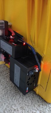
 
Last edited:
@Chargery See above if you can possibly understand what I am trying to say? Basically I have seen my load cut off with my over charge cut off. I had a cell hit charge threshold to make sure it cuts off charge and as it did cut the charge off it also cut off my load. Load is DCC-300 original and charge is DCC-100 recently purchased as separate port.
Thanks!
 
Something additional to add to the above I am seeing an voltage drop from input and output. INPUT @ 13.26 with an OUTPUT @ 12.82.
I know the fan would not draw that much current? The Fan does seem to run a lot not sure if it is temp activated?
 
Something additional to add to the above I am seeing an voltage drop from input and output. INPUT @ 13.26 with an OUTPUT @ 12.82.
I know the fan would not draw that much current? The Fan does seem to run a lot not sure if it is temp activated?
MOSFETs typically have around a voltage drop of ~0.6V, being they are semiconductors, not conductors, hense the cooling fan, the higher the current the greater the losses, in the case of a 100A load at 0.44V.drop, the loss would be 44W, or 3.35%. At lower current the losses would naturally be reduced, which makes higher nominal battery voltages more efficient for the same given load .
 
MOSFETs typically have around a voltage drop of ~0.6V, being they are semiconductors, not conductors, hense the cooling fan, the higher the current the greater the losses, in the case of a 100A load at 0.44V.drop, the loss would be 44W, or 3.35%. At lower current the losses would naturally be reduced, which makes higher nominal battery voltages more efficient for the same given load .
Dang that is true do not know why that did not calculate in my brain being MOSFETs having some voltage drop. Will monitor it bit more still think it is much for no output draw.
 
Sorry, Tim, I dunno. I use Common Port config, never had any such issues, everything works tickety boo for me.
Has your fan stayed on mostly with the DCC 300's? Notice a .4 - .5 voltage drop between input and output?
 
I've only had the fan s come on a couple of times and they do not stay on for long. The powerhouse never exceeds 28C temp and my system design is such that there is never a huge load on any BMS - 5 Packs in the bank eh...
 
I've only had the fan s come on a couple of times and they do not stay on for long. The powerhouse never exceeds 28C temp and my system design is such that there is never a huge load on any BMS - 5 Packs in the bank eh...
Interesting mine has been in around same temp times more but even lower and the fan is running constantly. Also the load is only an ICECO fridge/freezer pulling 37watts off and on.
 
Interesting mine has been in around same temp times more but even lower and the fan is running constantly. Also the load is only an ICECO fridge/freezer pulling 37watts off and on.
Have you tried emailing Jason .... doesn't seem like you should be getting the fan with that low a load.
 
Have you tried emailing Jason .... doesn't seem like you should be getting the fan with that low a load.
Bob, I will try to email him as I do not think he has time to monitor forums for sure. I have been testing it since Fri. and running the battery down and noticed this. I was waiting for this cooler weather we have coming to see what happens. Then I will provide some feedback and questions back to him. Good point thanks!
 
Update - If I looked in my notes sooner I would have found the DCC specifications that list the fan start temp (105.8F = 41C). So it seems something really is wrong with my DCC 300. Really odd things going on that I discovered yesterday and don't know how to even explain it to get some opinions.

I have emailed Jason so might take him sometime to respond back.
 
Have you tried emailing Jason .... doesn't seem like you should be getting the fan with that low a load.
Jason seems to have taken long vacation. He's always emailed back pretty quickly but it's been awhile now hadn't heard from him. From what I can tell the fan should not be on until a set temperature that is pretty high I think 105 F. I've not gotten over 87 F.

Other issue seems it's not even coming on I've found out things are working due to the power traveling backwards from the charge DCC that completely has me little confused and seems this way your basically defeated the whole reason to be doing a separate port setup.
Sorry, I'm not using the DCC .... so, I can't tell you what is normal.

I don't know where Jason was before, but now, I think it is the fall festival holiday there.
 
Whenever making a decision between two or more options I make a list with columns like spread sheet, then check against attributes to determine which is the better method, product or whatever, just my way of avoiding mental clutter thereby reducing the possibility of making the wrong decision. Sometimes through ignorance or lack of insight this method fails me, hense the decision to switch out the current BMS, after seeing the correlation between battery failures and MOSFET control BMS's.


My plan is to use both ports with a slight variation, the charging port will drive a small relay, over a NO contact of that relay will be a resistor loop connected across the RTS input of the SCC, this will cause an out or parameter fault when the relay drops, thus disabling the SCC , a manual reset is required to restore charging.

The load contactor, whichever I decide to use, must for my purposes be a one shot fail safe configuration requiring manual reset as well, primarily because I'm often away and would rather return to a partially discharged battery, than the remains of a catastrophic battery failure, to avoid going of on an off topic tangent I will create a seperate thread (Fail safe BMS? ) on this. please do not ask follow up questions here.


The DCC is a convenient plug and play setup which includes optional features which make it very attractive, so long as it meets the design criteria of the user, unfortunately as my personal needs demand a divorce from semiconductor disconnect, I haven't at this point, found a way to circumvent that worst case scenario using the DCC.
If you are looking for manual reset, a DC circuit breaker with a shunt trip might fit the bill....
 
Testing my DCC's and charging the battery until I hit over charge protection I've noticed in my separate port configuration that both the charge and load DCC cut off. I do have an old original load DCC and not sure if maybe the input of the + & - matters if it goes in on the left side or right side. The cable used came with the specified separate port charge DCC-100 that I order this year. I have also noticed that the load DCC has only one LED (status) that does not come on. I am getting power through it. Any thoughts? View attachment 64375
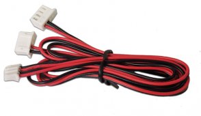
hi sorry for delay, i am very busy for a long time. i guess you have BMS8T and 4S battery, from above picture, the DCC-100 is for charge cut off and DCC-300 is for discharge cut off, but the separate control wire connection is wrong, from ISO board to DCC, there are a split wire as below,
DCC-CableSeparate.jpg
the wire has a 4pin connector, that is conneted to ISO board, and there are two 2pin connetor, that is connected to charge DCC and discharge DCC separately,
please check the below picture, find which 2pin connetor connect to charge DCC or discarge DCC
ISOPOWER12.jpg
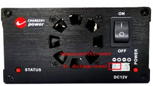
For BMS8T,the up 2pin connetor should be connected to discharge DCC, down 2pin connector should be connected to charge DCC, on DCC side it looks like as below,
8TSeparateControl.jpg

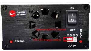
For BMS16T and BMS24T, on separate port DCC control wire should be as below,

ISOPOWER13.jpg
16T24TSeparateControl.jpg
 
Something additional to add to the above I am seeing an voltage drop from input and output. INPUT @ 13.26 with an OUTPUT @ 12.82.
I know the fan would not draw that much current? The Fan does seem to run a lot not sure if it is temp activated?
when DCC cut off charge or discharge, the voltage drop from input and output is caused by internal surge suppressing circuit, means mosfet is turned off, although the voltage is 12.82v on output, but the battery don't be charged or discharged. when the STATUS LED on, means mosfet is turned on, the voltage on input and output has not difference, battery can be charged or discharged.

when internal temperature over 41 C, the fan will turn on, and powered by battery, the fan current is around 0.2A at 12V. when udner 38C, the fan will turned off.
 
hi sorry for delay, i am very busy for a long time. i guess you have BMS8T and 4S battery, from above picture, the DCC-100 is for charge cut off and DCC-300 is for discharge cut off, but the separate control wire connection is wrong, from ISO board to DCC, there are a split wire as below,
View attachment 68384
the wire has a 4pin connector, that is conneted to ISO board, and there are two 2pin connetor, that is connected to charge DCC and discharge DCC separately,
please check the below picture, find which 2pin connetor connect to charge DCC or discarge DCC
View attachment 68385
For BMS8T,the up 2pin connetor should be connected to discharge DCC, down 2pin connector should be connected to charge DCC, on DCC side it looks like as below,
View attachment 68386

For BMS16T and BMS24T, on separate port DCC control wire should be as below,

View attachment 68388
View attachment 68387
Jason,
Thank you so much for this detail. Understand you are busy and think you all had a Holiday. Should be good reference for someone else in future. I do have BMS8T and 4S battery, I did change the wiring after I was looking through some photos etc. I did change it for discharge on the DCC 300 and Charge on the DCC 100 as it was designed to be. This will only allow it to turn correct one on and off. But seems my problem has been the DCC300 will not come on. All power is back flowing through the charge DCC100.
 
Last edited:
Back
Top