diy solar

diy solar

Chargery BMS, DCC (Solid State Contactor) thread.

It looks like it's on the opposite side from the terminals ... here's a picture from the web page.

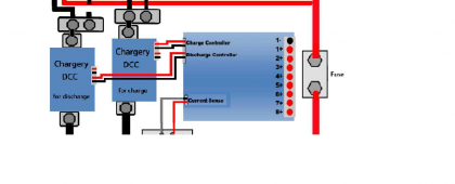
They are bi-directional, so the connections shouldn't matter .... but I attached a common a separate port diagram from the web page.

The other thing to be aware of ... if you are switching inverter power ... is that the pre-charge circuit only works when the DCC is manually powered up ... it doesn't work if the BMS turns it off and back on. I hope they fix that one of these days.
If you search on Youtube there is a nice video where the guy used a Chargery delay board to automate a pre-charge circuit.

View attachment 47946View attachment 47947View attachment 47948
My 100A DCC does not have a fan, I do not know if that is normal. Seeing that the control port has 4 pins for separate port DCC, does it matter which side I use for charge or discharge?
 
Don't know about the fan for sure, but it is probably just not needed.
I'm not up to speed on a common port configuration, but the wiring is covered pretty thoroughly in the manual.
 
Don't know about the fan for sure, but it is probably just not needed.
I'm not up to speed on a common port configuration, but the wiring is covered pretty thoroughly in the manual.
The wiring diagram does not indicate which side is charge or discharge. I am talking about separate ports DCC actually.
 
I've searched and searched and cannot find an answer, is the dcc common port capable of stopping the charge and discharge separately? If i've just overlooked the discussion on this please feel free to link it rather than reinventing the wheel.
 
You need to have a separate port configuration to cut them off independently.
 
You need to have a separate port configuration to cut them off independently.
problem is I don't have a separate charger, my inverters are my chargers, any insight in how to wire that?
 
Please tell us what model inverter / charger you have. They are all different as far as how to control them.

As far as I know, Victron is the only inverter / charger that can have independent remote control of charge and load.

I looked hard at the Samlex EVO, but it could control one or the other, but not both .... maybe that's changed since I looked at them?

This is the primary reason I chose to have independent charger and inverter.
 
system I'm using now is 3x5kw 240v mppsolar inverters stacked into 4153p + 1 lv5048 running my 120v loads in single phase. the inverters have built in mppt cc hooked to a 20kw solar array split into 5x 4kw strings. each inverter also has a ac to dc charger for when I run my backup gen
 
When Inverters/SCC's are on the Same Common DC bus as the battery bank, then the system is common port.
If SCC and Chargers are on One DC Bus and connected to batteries and Inverter(s) are connected on another DC Bus for output only, that is a separate port.
 
When Inverters/SCC's are on the Same Common DC bus as the battery bank, then the system is common port.
If SCC and Chargers are on One DC Bus and connected to batteries and Inverter(s) are connected on another DC Bus for output only, that is a separate port.
yes I understand this. my question was if there is a way to wire the chargery so that it controls charge and discharge separately on a common port system. whether by using a common port unit or a separate port unit.
 
When Inverters/SCC's are on the Same Common DC bus as the battery bank, then the system is common port.
If SCC and Chargers are on One DC Bus and connected to batteries and Inverter(s) are connected on another DC Bus for output only, that is a separate port.
I have mine on the same DC bus .... but turn them on and off via remote control.

I don't know that MPP Solar device, but I seriously doubt if it can be remote controlled to shut off charge and load independently. Maybe someone who know it will check in an let you know.

The Chargery is capable of this .... The inverter / charger is what determines if it is possible.
 
yes I understand this. my question was if there is a way to wire the chargery so that it controls charge and discharge separately on a common port system. whether by using a common port unit or a separate port unit.
without 2 DCC the 1 DCC will shutoff the charger and inverter (battery) at the same time. The chargery itself is capable of separate port, you gotta have 2 relays to control the charging and inverting separately
 
Last edited:
ok guess that answers my question. will continue my search for an affordable high amp fet based common port bms then. I had hoped that chargery had wired directionality into their dcc units.
 
I designed a system in my head before I knew much about how "most" people set up their systems ... but I still like my way of doing it ... It just seemes contrary to me to design a system where the load would be cut off when a high voltage disconnect happens .... or that the charge will be cut off when you have a low voltage disconnect. It also didn't make any sense to me to switch the main DC when devices could be turned on and off remotely with a very low current relay.
I also don't have any problem with inverter pre-charge when turning the system back on since I only connect it once and after that just turn it on and off if needed.

The remote control strategy works well for me .... but doing that requires knowing you want to do that before purchasing equipment .... and ... I have a more simple system than some because I only have one battery pack .... and the Chargery BMS is the perfect BMS for using this strategy.
Managing multiple packs becomes a different ball game.
 
ok guess that answers my question. will continue my search for an affordable high amp fet based common port bms then. I had hoped that chargery had wired directionality into their dcc units.
The port that the relays connect to has 4 prongs. my understanding is that 2 of those prongs (going to one relay) are activated at one time. The other 2 prongs are for the other relay. So I’d assume that each set of prongs acts like a separate port. Meaning that only 2 prongs to one relay are activated at a time
 
yes I understand this. my question was if there is a way to wire the chargery so that it controls charge and discharge separately on a common port system. whether by using a common port unit or a separate port unit.
Honestly, I don't understand why one would do that.
A battery pack is either charging or discharging at any given time.
IF the BMS has to cut that function while it is occuring, the shuts the line off.
BUT, this is NOT the BMS' real job, it is a Failsafe and cell protector. It will Cutoff because it is a "Protection Function".
Any/All SCC's should be programmed to cutoff & optionally go into float mode when the appropriate voltage & termination amperage is reached. (0.05C os highest capacity battery pack)
This also applies to the Inverters & Chargers connected to do their own cut-offs. This is a primary reason for ensuring your ensure system is voltage calibrated & compensated.

Separate Port is most typically used for EV's/LEV's and similar applications where there is no Solar and most often an external/independent charger system and where an inverter may or may not be also included. This also allows for Regenerative braking charge input while continuing output simultaneously.

The Charge & Discharge signals for the relays or DCC can be used with opto-couplers and similar as well. Many Inverter/Chargers can use On/Off signal from a low voltage relay to enable/disable charging or inverting. Some have even done similar with their SCC's and it's all been discussed here in the forum.
 
I designed a system in my head before I knew much about how "most" people set up their systems ... but I still like my way of doing it ... It just seemes contrary to me to design a system where the load would be cut off when a high voltage disconnect happens .... or that the charge will be cut off when you have a low voltage disconnect. It also didn't make any sense to me to switch the main DC when devices could be turned on and off remotely with a very low current relay.
I also don't have any problem with inverter pre-charge when turning the system back on since I only connect it once and after that just turn it on and off if needed.

The remote control strategy works well for me .... but doing that requires knowing you want to do that before purchasing equipment .... and ... I have a more simple system than some because I only have one battery pack. Managing multiple packs becomes a different ball game.
Yes, wish I would have thought of that. My inverters do not have an on/off switch to turn off with a small relay. They don’t have anyway to communicate with the bms.
As for my charger I wanted to make sure I was cutting off the power the PV panels were providing rather than cutting off the dc from the battery to the charge controller. And also rather than cutting off the charge controller directly while it was charging. I know some charge controllers are fine being cutoff while pv power is going through them but it didn’t seem right to me. Only way to do that is with a relay that can handle the high amperage of my array.
 
Honestly, I don't understand why one would do that.
A battery pack is either charging or discharging at any given time.
IF the BMS has to cut that function while it is occuring, the shuts the line off.
BUT, this is NOT the BMS' real job, it is a Failsafe and cell protector. It will Cutoff because it is a "Protection Function".
Any/All SCC's should be programmed to cutoff & optionally go into float mode when the appropriate voltage & termination amperage is reached. (0.05C os highest capacity battery pack)
This also applies to the Inverters & Chargers connected to do their own cut-offs. This is a primary reason for ensuring your ensure system is voltage calibrated & compensated.

Separate Port is most typically used for EV's/LEV's and similar applications where there is no Solar and most often an external/independent charger system and where an inverter may or may not be also included. This also allows for Regenerative braking charge input while continuing output simultaneously.

The Charge & Discharge signals for the relays or DCC can be used with opto-couplers and similar as well. Many Inverter/Chargers can use On/Off signal from a low voltage relay to enable/disable charging or inverting. Some have even done similar with their SCC's and it's all been discussed here in the forum.
there are any number of reasons...

99% of all solar setups that are already in existence are common port. Sometimes we have seperate solar charge controllers, but virtually every system will still use an inverter charger that needs common port control.

the reasons why you would want the ability to stop charge and discharge disparately in these systems is simple. there are MANY situations where you need to cutoff charging w/o affecting discharge. ambient temperature below freezing, 1 cell slightly to high/running (very common in commodity cells) Etc.
 
Back
Top