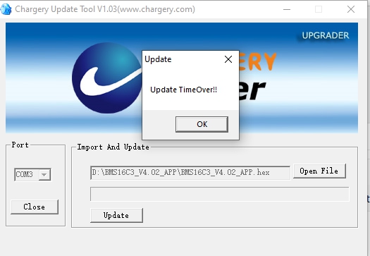
This was only checking with a power supply , and it's too early to tell how well the SOC is going to track. I am doing a full charge and will run some tests on the SOC and WH tracking .... from what I am seeing the update seems like it was very effective.
The SOC counter is still not very useful.
Thanks to my Thrash testing (still happening) I forced all my packs down to LVD. Kicked on the Genset, dialed up to 75A charge flipped the switch on BMS' and they started charging from "0 % SOC" what a "trip" the packs took... within 3 hours 2 packs reported 100% SOC (one 175AH and one 280AH) , yet cells were hovering around 3.380V ? The other two packs reported different SOC's.
A kick in the pants result !
Here's the weird part... I did NOT expect at all...
The 2x 280AH Packs, one says 100% the other says 40% BOTH have their cells floating around 3.35-3.39 or so (pretty close across the board) so WTH is up with that ? Both had hit 0% SOC !
BUT - BUT... A lurkin issue ? Here's the rub, NONE of the battery packs actually hit 0% SOC. They were still reading 24.5+ ish volts per pack. LVD Cutoff is set at 3.00V. Each pack had ONE cell hit 2.99V and tripped the disconnect claiming 0% SOC. Now even Weirder... The Pack that did not reset to 0% SOC tripped the exact same way by one cell hitting 0% SOC yet that did not reset the SOC counter to 0% ???? Call me confused ! I mean seriously, WTF is up with that ?
More ODDNESS:
So now here I am charging 4 packs, the 2x 280's and the 2x175's (those used ShunBin cells.
They are on a Common DC Bus in parallel, battery cables are all 4/0 from pack terminal to busbars, to SCC & Inverter. All of the cables are the same length (within 1/8"). So that is all uniform and good, no wire/connection issues, all triple checked for resistance etc.
The two 280AH packs started sucking in 25A to 27A each at the start leaving the rest going into the pair of 175's. Within an hour or so, the 280's took a bit less while more was going into the 175's. Alright, that is interesting but makes sense based on capacity and DOD.. sorta... All the cells in all the packs were happy as clams with <15mv difference during the charge process.
3 hours after starting two packs report 100% but still sucking up the juice as I mentioned above with none of the cells over 3.35 ish so keep charging, now I am seeing the 280's taking in less Amps (as expected) and more going into the 175's so now they are topping up faster & staying fairly even too... again this is not unexpected... THEN the Top WALL ! Holy Macaroni... Those 175's ! they hit the point where all the cells were tickling into 3.4V and sure enough ONE Blighter decided to take off and suck up juice faster than everyone else and away we go to 3.65 and TRIP HVD, pack cuts off and cells settle for 5 minutes and drop below 3.55 and charge restarts and within 30-45 seconds were back to 3.65 and trip again. I can see the Active Balancer shifting the juice with the cell voltages showing that. Now I am seeing divergence up to 200+mv (I played with the setting to see how far they'd get out of whack).
Now as the one pack is playing the HVD edge, the amps are being shifted to the actives while that one kicks off... Great, doing as it should... Now all of a sudden one of the new 280's does that, same deal, one cell hit 3.65 and trip ! Now I have Two Flippers a Flappin - genset is not really impressed with the fluctuating Amp Demands but it's no baby (7200/9000W) so, forward ho ! EVEN MORE STRANGE ! That damned SOC nonsense... The 175's both reporting 99% (they both zeroed) the 280's have separate ideas. What's WORSE, is now the divergence between the Speedy Cell and the slow poke is 200+mv when charging (not when static or discharging). SO the Speedies are killing the ability to get them all up to 3.5V... 3.4 is as far as they will go before speedy decides to run to the finish.
NONE of the IR reported by the BMS' are out of whack, sure there is a bit of difference but nothing serious, in the "working voltages: 0.8 to 1.0 is not much variance. When the LVD was triggered, the one cell in the 175's was reading 2.5 IR, the one 280 that tripped LVD was at 1.8 while the other 280 that Tripped LVD was 1.1.
My YR1030 IR Tester is out of commission, the new YR1035+ should be here I soon I hope... It is traveling with cells, BMS (not chargery) and other equipment. Once I get that, I can re-verify the IR as indicated by Chargery compared to the YR Tester...
The 15V/50A adjustable PS is en-route. Once it arrives, I'll top cells up manually to 3.5 and start another round of tests.
Ironically, I have tinkered the bejesus out of my Midnite Solar Charge Controller and the WizBangJr shunt monitor and it's more accurate about SOC and such, and those have no programming for Lithium based batteries ! which is a tremendous PITA because of the flat voltage curve.
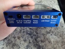
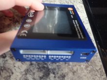
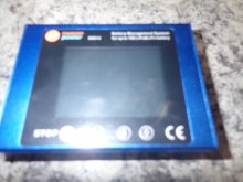
The Setup:
BMS8T-300's. DCC-300's, Chargery Shunt, 1 QNBBM-8S Active balancer per pack.
BMS is powered via the BMS Harness attached to battery. I have the power plugs now, so I was thinking of running leads off the battery terminal posts to the BMS so that it is not powering itself through the harness. Will that make any difference anywhere ? I dunno. Can't hurt.
I hope my observations help folks...
There are many things that are coming out of my Thrash Testing, some good, some not so much and a couple that downright tick me off. At least, doing this kind of harsh test in a controlled situation is better than learning the hard & wrong way. The kicker is, now the LFP is my Primary Battery Bank and the FLA's are secondary (saved my butt at 23:30 hours) when the LFP all kicked 0% SOC and all I had to do was flip a switch over...


postimg.cc