


You are using an out of date browser. It may not display this or other websites correctly.
You should upgrade or use an alternative browser.
You should upgrade or use an alternative browser.
Chargery DCC
- Thread starter Dyotat100
- Start date
sunshine_eggo
Happy Breffast!
Why would you put it on the (+)?
Did you follow the diagram?

22W may be because your battery is full?
Poor solar?
You damaged it when you hooked it up wrong?
Did you follow the diagram?
22W may be because your battery is full?
Poor solar?
You damaged it when you hooked it up wrong?
There was a reason to put it on the positive side. I ordered the inline ISO board.
I have had the stuff for almost a year and working on finishing it.
Solar is putting out 100 amps 12v and I was going to use the DCC to turn off the solar. Only
I have had the stuff for almost a year and working on finishing it.
Solar is putting out 100 amps 12v and I was going to use the DCC to turn off the solar. Only
Attachments
sunshine_eggo
Happy Breffast!
Sounds like a question for Chargery then.
Bob B
Emperor Of Solar
- Joined
- Sep 21, 2019
- Messages
- 8,646
The Chargery BMS is contactor based and in no way is capable of LIMITING the charge current .... either it is charging or it is not.
So ... If you aren't getting enough charge current, you would need to be looking at other aspects of the charge circuit.
If charging was disabled by the BMS .... that would be a different issue.
So ... If you aren't getting enough charge current, you would need to be looking at other aspects of the charge circuit.
If charging was disabled by the BMS .... that would be a different issue.
OffGridInTheCity
Solar Wizard
I have serveral Chargery(s). One thing - you HAVE to have the temp sensors plugged in and they must 'work' (can't be damaged) for Chargery to work.
RCinFLA
Solar Wizard
- Joined
- Jun 21, 2020
- Messages
- 3,565
BMS's and the Chargery MOSFET based DCC use N-channel MOSFET's because they provide lower Rs for cost of MOSFET than a P-ch MOSFET.
This means N-ch MOSFET gate must be pulled 12-15v higher than source of turned on MOSFET, which is why they are on negative battery line.
It would be possible to put on positive line if the unit provides its own boosted supply to provide 15v above positive battery but I doubt they would do this. Then there are other control line items that need to be ground (negative line) referenced which would have to be isolated from MOSFET drivers.
A lot of extra expense.
RCinFLA
Solar Wizard
- Joined
- Jun 21, 2020
- Messages
- 3,565
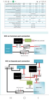
Page 4 of DCC manual states normal connection is DCC switch put in Negative battery line.
"Chargery DCC installation details.
Warning:
1. When installing Lugs, DO NOT Allow the lugs to make contact with the DCC Casing.
2. Do not allow the lugs to touch each other & short out.
3. The CHARGERY DCC should be installed on the battery negative, after the shunt. The shunt
should be between the DCC & Battery itself. If fit with our ISO board, it can be installed on
battery positive side."
There is an optional ISO board that bootstraps control lines above battery positive to give ability to put DCC switch in positive battery line. This is not the normal hookup with the Chargery blue BMS box.
To make things worse, the manual on page 8 shows a connection diagram showing the ISO board option, BUT MANUAL DOES NOT HAVE A CONNECTION DIAGRAM FOR NORMAL NON-ISO BOARD HOOKUP.
May have damaged DCC if put in positive battery line without optional ISO board.
Very poor manual, inducing a user to hook it up wrong unless they carefully read and understand it.
I got it to work with help from chargery. Turns out that you need to turn off BMS. When I turned it on the ISO board lights came on. Then turned on the DCC and lights came on.
So I put it back inline on positive side of my solar feed. I used my power supply to test it. Works great. Had it set at 3.4v off and 3.38 on. Would cycle on and off. Can't wait to see how it does with the solar tomorrow.
With a 100 amps coming in most of the day I was having to bump up the voltage to 14.7 to keep it from going into float. It would go into float below 40% charge. Fine if I'm around and able to check on it but can't leave it alone. I had the vitron setup at 14.1 and 13.60 float. Worked great on 20-30% charges with 70 amp peak. 100 amp by 9 am changed that. Tomorrow is the test.
Thanks for all the input
OffGridInTheCity
Solar Wizard
Congrats! Must feel good / sigh of relief that after paying $ and hooking it up its actually working!I got it to work with help from chargery. Turns out that you need to turn off BMS. When I turned it on the ISO board lights came on. Then turned on the DCC and lights came on.
")
Yes it does. I have been using 12v 560 ah battery with no protection. Have inverter set to turn off at 11.5 volts. Had charger fine tuned pretty good also.
Solar was pretty good but the more amps I run the harder it has been. I feel pretty good now that it turns off exactly when told to.
I order another Chargery BMS and 2 DCC. Going to build another pack.
Solar was pretty good but the more amps I run the harder it has been. I feel pretty good now that it turns off exactly when told to.
I order another Chargery BMS and 2 DCC. Going to build another pack.
Steve_S
Offgrid Cabineer, N.E. Ontario, Canada
When the Manual was written, the DCC was still being developed with our members involved. Once the DCC was developed the manual was updated accordingly. Later the DCC was updated and the ISO Board and other components added and at that time the ability to put the DCC on the (+) side became the preferred method. Jason made updates to the docs after that, as I am not maintaining their DOCS.
My involvement with Chargery was my own initiative to redo their manuals because the previous Chinese to English (Google Translated Mess) was "Horrid" and required decoding, That process and other things like being one of the rare BMS' at the time having Hi & Lo Temp Sensing and external interface capabilities, which were not common then. The DCC Evolved from a need to use non-Electro-Mechanical Energy Guzzling relays. A couple of us started to get Solid State Relays and even commissioned custom ones and experimenting and Jason of Chargery was convinced into creating such in-house. All of the Historical Threads (Really Long) are on the forum.
PS: I tried to help people with Chargery and most were really good but after a few serious cases of belligerence and assorted accusations and general "krap" I stopped trying to help with it in general. I've always been an OpenSource Shareware kind of guy but it appears that is not acceptable to many anymore, so it is what it is.
Have Fun & Good Luck.
BTW: Here are the Chargery Settings which I used for a 5 Pack Battery Bank consisting of 3x280AH & 2x174AH.
| Setting | Default | My settings | NOTES |
| Over charge P Voltage | 3.65 | 3.65 | |
| Over charge R Voltage | 3.55 | 3.55 | |
| Over charge Current | 50 | 86A / 150A | 0.5C rate for 174AH / 280AH |
| Over Discharge P Voltage | 3.00 | 2.65 | CUTOFF Trigger |
| Over Discharge R Voltage | 2.00 | 2.75 | Release @ this V. |
| Over Discharge Current | 300 | 175A / 250A | 1.0C Rate for 174AH / 280AH |
| Low SOC cutoff | 20% | 0% | forces cutoff @ % (faulty) |
| High Temp cutoff | 50C | 70C | |
| Diff of Batt Temp | 10 | 15C | |
| Diff of cell Voltage | 30mv | 200mv | Unmatched cells drift, |
| Temp Unit | C | C | |
| Key Beeper | ON | ON | |
| LCD Backlight | 10 | 10min | |
| Cut off Delay Time | 10 | 10S | |
| Current Calibration | -SET- | ||
| Temp Alarm | ON | ON | |
| Cell Empty Voltage | 2.50 | 2.50 | |
| Cell Full Voltage | 4.20? | 3.65 | |
| Default Setting | Enable | ||
| Balance Parameter | -SET- (OFF)* | Passive is ON charge only, start at 3.40V, 30mv diff. | |
| Battery Capacity AH | 1 | 174 | 280 | Label Value of cells |
| Battery Power WH | 1000 | 4554 | 7168 | FORMULA (NominalVolts * #ofCells * RatedAH) (3.2*8*280=7168) |
| Low Temp cut off in Charge | 2C | 2C | |
| Low Temp cut off in Discharge | -10 | -10C |
Thanks
Pretty close to what I have been running. Battery has been together for about a year. I used it for a weekend in my 5th wheel camping last March. Then it sat until a couple of months ago when I picked up some solar panels. I have been experimenting with the panels using battery and my inverter.
I'm waiting for my inverters for house and will take it off the grid. SCE is out of control with rate increases.
When the Manual was written, the DCC was still being developed with our members involved. Once the DCC was developed the manual was updated accordingly. Later the DCC was updated and the ISO Board and other components added and at that time the ability to put the DCC on the (+) side became the preferred method. Jason made updates to the docs after that, as I am not maintaining their DOCS.
My involvement with Chargery was my own initiative to redo their manuals because the previous Chinese to English (Google Translated Mess) was "Horrid" and required decoding, That process and other things like being one of the rare BMS' at the time having Hi & Lo Temp Sensing and external interface capabilities, which were not common then. The DCC Evolved from a need to use non-Electro-Mechanical Energy Guzzling relays. A couple of us started to get Solid State Relays and even commissioned custom ones and experimenting and Jason of Chargery was convinced into creating such in-house. All of the Historical Threads (Really Long) are on the forum.
PS: I tried to help people with Chargery and most were really good but after a few serious cases of belligerence and assorted accusations and general "krap" I stopped trying to help with it in general. I've always been an OpenSource Shareware kind of guy but it appears that is not acceptable to many anymore, so it is what it is.
Have Fun & Good Luck.
BTW: Here are the Chargery Settings which I used for a 5 Pack Battery Bank consisting of 3x280AH & 2x174AH.
Setting Default My settings NOTES Over charge P Voltage 3.65 3.65 Over charge R Voltage 3.55 3.55 Over charge Current 50 86A / 150A 0.5C rate for 174AH / 280AH Over Discharge P Voltage 3.00 2.65 CUTOFF Trigger Over Discharge R Voltage 2.00 2.75 Release @ this V. Over Discharge Current 300 175A / 250A 1.0C Rate for 174AH / 280AH Low SOC cutoff 20% 0% forces cutoff @ % (faulty) High Temp cutoff 50C 70C Diff of Batt Temp 10 15C Diff of cell Voltage 30mv 200mv Unmatched cells drift, Temp Unit C C Key Beeper ON ON LCD Backlight 10 10min Cut off Delay Time 10 10S Current Calibration -SET- Temp Alarm ON ON Cell Empty Voltage 2.50 2.50 Cell Full Voltage 4.20? 3.65 Default Setting Enable Balance Parameter -SET- (OFF)* Passive is ON charge only, start at 3.40V, 30mv diff. Battery Capacity AH 1 174 | 280 Label Value of cells Battery Power WH 1000 4554 | 7168 FORMULA (NominalVolts * #ofCells * RatedAH) (3.2*8*280=7168) Low Temp cut off in Charge 2C 2C Low Temp cut off in Discharge -10 -10C
You take your cells up to 3.65 volts? I was trying to do 80% cycle. I'm set at 3.41 volts
sunshine_eggo
Happy Breffast!
You take your cells up to 3.65 volts? I was trying to do 80% cycle. I'm set at 3.41 volts

Best LifePo4 charge controller settings known to man for Maximum Service life and Minimum battery stress!!! 5,000-10,000+ cycles?
---ORIGINAL TITLE---- Best charge controller settings to achieve 10%-90% usage on lifepo4 ? EDIT-UPDATE and the ANSWER to this question. . . This post is a accumulation of all the great and wonderful information given to me by all the great people on this thread. I consolidated all of this...
 diysolarforum.com
Steve_S
Offgrid Cabineer, N.E. Ontario, Canada
I never take my cells to 3.650, they are set to be at 100% at 3.425Vpc.
BMS is the Emergency Brake and is set accordingly relative to LFP Full Voltage Curve rather than the Working Voltage Curve of 3.000-3.400.
My Systemic window charges to 3.425 and does not go below 2.950 but does allow for Load Sag which can take it lower for a few moments should a heavy load surge pop up.
My SCC (Midnite Classic 200) is programmed to deliver that charge and is Voltage Corrected so that is what is actually happening at the "Battery Terminals". Also My Inverter/Charger (Samlex EVO-4024) is also voltage corrected to force cutoff at 2.635V per cell.
It is really important to know that whatever your SCC or Inverter system display is NOT Nescesarily what is seen at the Battery Terminals because with every connector, fuse, breaker, lug, there will be some loss in both Voltage & Amperage. Hence why I wrote a piece on Calibrating systems but few ever take the time to look and consider it.
Similar threads
- Replies
- 17
- Views
- 707
- Replies
- 4
- Views
- 193
- Replies
- 11
- Views
- 337
- Replies
- 1
- Views
- 232