wpns
Solar Joules are catch and release
I did essentially the same thing with a 120V coil relay,one side to L1 and the other switched to neutral thru the Gen dry contact.


One should have been included with the inverter that fits inverter, and another with the chargeverter that fits it… I tested both and they both work perfectly … just liked the dry contacts on inverter cause I could use SOC to turn on or off.Ok I’ll order the contactor and wire up. Thanks for all the help..I’ll let you know how it works. I’m in the dark right now. I forgot to plug in the chargeverter and now batteries are dead. Erggggg
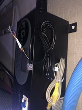
Do you mean the RJ45 like the picture just hook to those with one side of contactor?One should have been included with the inverter that fits inverter, and another with the chargeverter that fits it… I tested both and they both work perfectly … just liked the dry contacts on inverter cause I could use SOC to turn on or off.
Edit: the inverter just used small 18gauge wire … was not even a special cable the more I think about it .
One should have been included with the inverter that fits inverter, and another with the chargeverter that fits it… I tested both and they both work perfectly … just liked the dry contacts on inverter cause I could use SOC to turn on or off.
Edit: the inverter just used small 18gauge wire … was not even a special cable the more I think about it .
Yes that is the cable for dry contacts .. see below the manual …Do you mean the RJ45 like the picture just hook to those with one side of contactor?


Yes I have to use voltage. I have EG4 every thing but I think I can not use SOC at all if batteries are connected to inverters.I assume your inverter has comms setup ? So you will have to use battery voltage … (unless you have eg4 interverter also)
So yours has the neutral wire connected to dry contacts on eg4?I did essentially the same thing with a 120V coil relay,one side to L1 and the other switched to neutral thru the Gen dry contact.
Yes, neutral connected to one of the dry contacts, relay coil to the other.So yours has the neutral wire connected to dry contacts on eg4?

More than likely your battery(ies) have not been fully charged and the BMS is reporting an incorrect SOC. Periodically the battery(ies) need to be charged where most (hopefully all) the cell voltages exceed 3.45 VDC (better to at least 3.5 VDC) and the entire battery reaches 56 VDC (3.5 VDC x 16 cells). The BMS will reset the SOC to an accurate 100%.I notice on my battery at 17% SOC voltage is 52.4 and 100% SOC is 54.6v. How do you guys get the dry contacts to operate when it has to have a 5v difference? I’m only looking at 2.2v difference unless I want to run battery all the way down I guess. Not sure what the voltage would drop down to at 5% SOC. Are you guys all using SOC and not using the BMS communication with your inverters?


Should I set my chargeverter to 56volts and let it charge all the way up tonight? And discharge to get it all the way to dead 0% today? Will this reset the BMS?More than likely your battery(ies) have not been fully charged and the BMS is reporting an incorrect SOC. Periodically the battery(ies) need to be charged where most (hopefully all) the cell voltages exceed 3.45 VDC (better to at least 3.5 VDC) and the entire battery reaches 56 VDC (3.5 VDC x 16 cells). The BMS will reset the SOC to an accurate 100%.
Depending on your charge/discharge cycles and depth of discharge you may have to more often manually monitor and control the charging process as over time the BMS reported SOC will drift and over time become less accurate.
View attachment 231356
View attachment 231357
The BMS is "calibrated" at 100% since that's a known endpoint for voltage. Similarly you can "calibrate" by going to 0% low voltage cutoff. Most people find the first method easier.Should I set my chargeverter to 56volts and let it charge all the way up tonight? And discharge to get it all the way to dead 0% today? Will this reset the BMS?
No I get it. I’m still uncertain of the 3 contacts on the dry contact cable which one or ones to hook up? Do you only use common and No/or Nc depending on your contactor?Just to clarify, I could have used 120v .. I picked both hot wires to prevent any power from getting past this relay till it was on. Meaning I did not want L2 to bypass the relay and be live all the way to chargeverter… based on the wiring diagram of chargeverter it would not do anything, but sometimes weard things can happen when you only have stuff half hooked up and expect it to be off. My connection type stops both L1 and L2 at this relay … that was my only reason, the relay supported it and so did 6000xp so I figured I would kill both lines here to stop anything from that line L2 line.
More of a preference … there is also no reason this could not be another power source, like the 48v battery or some other source… I picked this way cause it was easy as would surly exist if things are to be turned on .. otherwise there would be no reason to turn on it that power did not exist…
Ok great so I’ll just set my Chargeverter to 56 volts and let it calibrate. So back on your Chart the bottom should be 40v. So I should have a 16v swing. Wow my SOC is way off then. So it seems I should have a lot more battery life then I’m using now. Crazy. It’s a new system only had for 3 months. Not sure why I didn’t know that value?The BMS is "calibrated" at 100% since that's a known endpoint for voltage. Similarly you can "calibrate" by going to 0% low voltage cutoff. Most people find the first method easier.
Please don't try to associate SOC with voltage, those charts are a good reference for knowing approximately if your batteries are full or empty, but SOC is best measured with a Shunt that counts coulombs, or a BMS (which has a shunt that counts coulombs). Since any Shunt can have inaccuracies, and they will build up over time, you need to get your batteries to 'full' for a long enough time for the BMS (or other shunt) to determine that "OK, now I'm full" and reset the reported SOC to 100%.Ok great so I’ll just set my Chargeverter to 56 volts and let it calibrate. So back on your Chart the bottom should be 40v. So I should have a 16v swing. Wow my SOC is way off then. So it seems I should have a lot more battery life then I’m using now. Crazy. It’s a new system only had for 3 months. Not sure why I didn’t know that value?
Use Common and Normally Open unless you have a strange generator or relay configuration that you know wants Normally Closed.No I get it. I’m still uncertain of the 3 contacts on the dry contact cable which one or ones to hook up? Do you only use common and No/or Nc depending on your contactor?
Oh yeah they have a normally OPEN (disconnected normally dry contact) used with the common can be used to turn things ON when they switch to CLOSED circuit … (yellow/brown with common blue green)No I get it. I’m still uncertain of the 3 contacts on the dry contact cable which one or ones to hook up? Do you only use common and No/or Nc depending on your contactor?