diy solar

diy solar

Cheap chinese horizontal wind turbine, an in depth exploration.

moving to 5kw the voltage dropped to around 5 volts and the blades dropped in speed considerably.

Measurements for the 10 and 15 kw are close to 0 as my mmeter does not have a high enough resolution.

If my guess of "Y" connected elements was correct, 220V motor and one 220V element were in series at 5kW setting.

Drop in speed and zero current are consistent with expectation that the turbine produces almost no power.
Need much more wind (don't let it spin unloaded) or lower wattage load.

Do you have an incandescent light bulb? Could try one meant for 220V household use. For a heavier load, a 12V automotive tail light bulb. Heavier still, headlamp.
 
THank you brother, I will try. You do seem to go more in depth which is greatly appreciated. Please bare with me as I try to wrap my head around this all.

Just application of Ohm's law, and trigonometry for 3-phase (120 degree angles), things I learned in high school.

The resistive loads are easy to analyze.
Much more difficult are inductors and capacitors. Calculus, Euler's identity, imaginary numbers (which predict very real behavior.) Stuff I skipped in undergrad, finally mastered (or managed) in grad school.
But even that can be reduced to simple algebra, and maybe Pythagorean theorem. Yes, I use 2500 year old math to do much of my electrical engineering.
 
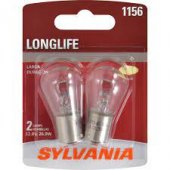
For a heavier load, a 12V automotive tail light bulb
OK, I will then go to the car shop tomorrow and get me a car tail light. You have been pointing in that direction long enough and now I am going to actually do it.
Can you give me an image please of what it is you are / I am looking for
 
Yes, I use 2500 year old math to do much of my electrical engineering
hahhaa Math is already that old, older perhaps And if it is not broken then no need to fix it.. For all I know only Isaac newton introduced calculus quite recently. But then again I know nothing ;)
 
The math which makes digital cell phones possible was invented hundreds of years ago. Before computers or electronics. Just for the beauty of it.

Leonardo invented a device to draw parabolas. So did I (in high school). We each used a different property of the curve.
I realized that if a string pinned to a board can draw a circle, and pinned at two ends can draw an ellipse, the parabola is an ellipse drawn with one end of the string pinned at infinity. That is, the segment of the string between the pencil and that pin at infinity doesn't change in angle as you move the pencil, is always orthogonal to one edge of the paper.
 
Measured how, clamp ammeter? AC or DC?
DC usually has offset. AC should be able to register zero.
You need to measure down to 0.01A or 0.001A, don't think there is much current from the turbine unless spun really fast.
 
You don't measure resistance when there is power on the wire, ever. That is why the meter was crying at you. This will destroy cheap meters.
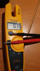
That fluke T5 measures AC amps (only) down to 0.1amp. I would expect something, but with the low voltage and wonky frequency with your test setup, I would not call this an issue.
 
OK, I will then go to the car shop tomorrow and get me a car tail light. You have been pointing in that direction long enough and now I am going to actually do it.
Can you give me an image please of what it is you are / I am looking for

Heater elements are constant resistance cold or hot.
Light bulbs increase in resistance 10x from room temperature to white hot.

For a household light bulb, put it in a lamp socket and connect wires to the plug (or I put wires in the screws of an outlet, from my stash of electrical stuff.)
Car tail lamp, need to connect some how. Some have wires that can be gripped with clips. Some can be soldered to.
 
OK, I will then go to the car shop tomorrow and get me a car tail light. You have been pointing in that direction long enough and now I am going to actually do it.
Can you give me an image please of what it is you are / I am looking for

1634924467383.jpeg

Anything like this. Just not LED.
 
Argg, how in the life of me do I connect a 3 phase system exposing 3 wires to such a puny lamp?

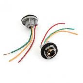
If you can buy a tail light socket.
1634924887258.jpeg

Or you can just hold the wires to the bulb. One wire, metal touching metal, to the metal base of the bulb (you can use electrical tape to hold it on), and touch one of the other wires to one or both of the two pads on the bottom of the bulb.

I should say, if you are touching any two wires (the copper parts) with your hands while it's spinning, you may get a bit of a zap or tingle. Nothing that will kill you at 70v (unless your hands are wet and it's spinning like crazy, but it will let you know when you touched them both.
 
Argg, how in the life of me do I connect a 3 phase system (turbine) exposing 3 wires to such a puny lamp?

Solder 2 wires to bulb, or 3 wires if it has both tail and stop filaments. Two solder blob connections on end, plus the shell.
Those two resistors can be used in series (blob to blob) for higher resistance lower wattage load across 2 wires of turbine.
Or, connect the 3 wires as "V", each wire to one of the turbine wires. Two bulbs can be connected (differently, to balance the uneven loads). Three bulbs suitably connected will put matched load on all three leads. That can be 3 "V", 3 blob-to-blob "delta", 3 blob-to-blob "Y" for various wattages.

Trick with a bulb is resistance changes as it heats up, so you do need to measure current not just voltage.


Check the specs, that meter may not register below 0.1A

Measuring ohms of load disconnected, and volts across load while operating, you will get at least some indication of wattage using light bulb. Your calculation will be about 10x high if brightly illuminated, less error if dim or not visible.
 
So that said, Hedges has done the excellent math. Taking my shot at it.

Heater is 23 ohms at 5kw.
Voltage when heater is on is 5V.
That gets me .217 amps (V/O).
So converting that into 3 phase watts (V × I × PF × 1.732) = 5 x .217 x 1 x 1.732 = 1.878 watts from the wind generator.

I might be very wrong here, or the load is so mismatched to the generator, it's dragging the generator down.


That's probably at least close.
But I'm unsure about your 3 phases with 5kW setting, which would only be one resistor connected (somehow) to two leads.
I would think 5^2 / 23 = 1.09W

Have you measured resistance? 23 ohms was my calculation.

Did you observe generator was dragged down considerably?
There would be some RPM that optimally harvests power at a given wind speed.
Hydro is simpler, given constant water feed, so fixed load rather than MPPT could be used.
Wind with simple rectifier into battery, no load until RPM produces voltage above battery, so can be somewhat reasonably tuned.
 
ave you measured resistance? 23 ohms was my calculation.
I tried, It fluctuated wildly and my mmeter beeped as if it was crying. It seemed even that the values (up to 200) and beeping were in line with the rpm of the blades. But that is just what I thought at that moment. No science behind that statement
 
Nooo!

You measure "ohms" with the heater disconnected from power source.
Measure "volts" connected.
 
Why I am both not surprised and sad at the same time? Weird feeling.
I will update my OP soon to give new comers to this thread a TL;DR

What was the wind speed?

You may get more either waiting for a windy day, or mounted on your car as a "wind tunnel"

iu
 

diy solar

diy solar
Back
Top