diy solar

diy solar

Class T fast acting or slow blow?

Roswell Bob

Solar Enthusiast
Joined
Dec 5, 2020
Messages
759
Location
Warner, NH
Do I need a fast acting or slow blow fuse for Growatt 6kW inverter? I'm looking at about 125A

I have used Class T fast acting fuses in industrial inverters. These inverters have resistor/relay charge limiting circuits though.

Those damn fuseholders are expensive :(
 
You don't need a class-t fuse for the inverter.
LFP batteries of 24 volts nominal or greater should have a class-t.
 
You don't need a class-t fuse for the inverter.
LFP batteries of 24 volts nominal or greater should have a class-t.
Yes, thank you. I understand I only need a Class T fuse that is rated to clear the fault current from battery array.

My concern was that fuse may clear when powering up the inverter because of inrush current charging caps on inverter bus. I think the JJN125 should be fine.
 
Yes, thank you. I understand I only need a Class T fuse that is rated to clear the fault current from battery array.

My concern was that fuse may clear when powering up the inverter because of inrush current charging caps on inverter bus. I think the JJN125 should be fine.
Usually there is a published trip curve for these fuses.
I'm have not heard of any problems using quick blow fuses.
 
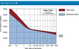
There is some margin. For the part in me that likes formulas and graphs, this is what Blue Sea gives for their fuses from 100 amps up to 400 amps with 160 VDC:

650FA26E-1D52-4A72-ADF3-429F53A9130C.jpeg
So as I read this chart, if I have a 125 amp Class T fuse will take between 500 and 625 amps to blow for what my inverter is spec’d for. Twice the rated power for less than 8 ms.

My 3000 watt inverter has SURGE OUTPUT POWER Of 6000 Watts (< 8 ms). Since my inverter is 3000 watts and 24 volts, I’d have a different fuse than that.
 
Inrush and need for precharge resistor:

From the capacitance of capacitors in the inverter (too big for my DMM to read!) you could determine a current/time of precharge surge.
Compare that to fast-blow portion of fuse curve. In some cases, it does look to me like it could blow.

The link above for 100A or a bit more (125A) looks like 700A for 10ms would blow it. 7 amp-seconds.

A 100mF capacitor is 0.1 amp-seconds per volt. Charged to 50V, 5 amp-seconds. I think that is similar to what I saw inspecting PCB of my Sunny Island. So it is on the threshold of blowing the fuse, unless resistance or inductance (or battery chemical reactions) spread the current over more time to allow heat dissipation.

I have a 350A fuse at the battery for two cables to two inverters. That's short circuit protection; the inverters themselves have breakers for overload protection. Two copies supply four inverters. From the graph, 3000A for 10 milliseconds, so 400mF in one inverter would bring mine to the threshold.
 
Oh, "Amp seconds" wouldn't be the correct units. Concern is Joules = Volts x Amps x Seconds deposited in fuse element.
Neglecting temperature coefficient of resistance (which leads to thermal runaway), it is Amp^2 seconds.
1400A for 5ms charges capacitor to same voltage as 700A for 10ms, but heating is I^2 x R, so double current is 4x power, half the time, twice the energy deposited.

Anything that reduces peak precharge current makes a big difference in heating and possible blowing of fuse. So include battery internal resistance and cable resistance in the calculation.
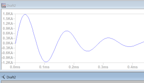
Very good analysis. There really isn't much limiting the current with a very tight layout with LiFePO4 cells close to the inverter bus. It isn't easy to measure the inrush current without a storage scope and a quality coaxial shunt. I think you are on the right track with a calculation. A simple simulation might be the best way to get idea. I don't know what bus caps are in the Growatt. Maybe I ask them. Are they here on page?
 
Very good analysis. There really isn't much limiting the current with a very tight layout with LiFePO4 cells close to the inverter bus. It isn't easy to measure the inrush current without a storage scope and a quality coaxial shunt. I think you are on the right track with a calculation. A simple simulation might be the best way to get idea. I don't know what bus caps are in the Growatt. Maybe I ask them. Are they here on page?
A fet based BMS in the circuit will protect your class-t fuse.
Also, I would guess a slow blow class-t fuse would still blow PDQ on a dead short.
 
With the cover off you can probably read capacitors and add them up. Mine might have looked like two batches in series, nP2S, can't remember for sure.
You could also measure charge rate through a resistor from a battery, determine capacitance.

An inrush-limit resistor seems prudent for Lithium.
Sunny Island documentation allows 100 Ah to 100k Ah lead-acid, doesn't mention an issue. Lithium would be through a supported BMS. I don't know what they do for inrush limit. Used to be LG RESU (48V). Sunny Boy Storage uses LG RESU-H (400V) which we've learned is a boost converter from a 48V battery so inherently current limited.

FET based vs. relay (one guy here has been welding Gigavac relays with his system.) What you want is a "precharge" command followed by "close relay", for when BMS automatically disconnects and later reconnects.

I could come up with a circuit using two high-current relays, but that's extra expense. Maybe FET & resistor, delay, relay.

Also, I would guess a slow blow class-t fuse would still blow PDQ on a dead short.

Got links to slow-blow & fast-blow class-T? I've only seen one family of curves. And I don't like that it is a single line per value, not a "must trip" and "won't trip" pair like I see for breakers.
 
Got links to slow-blow & fast-blow class-T? I've only seen one family of curves. And I don't like that it is a single line per value, not a "must trip" and "won't trip" pair like I see for breakers.
Just went hunting and I don't see any class-t that says anything like slow or time delay.
 
A fet based BMS in the circuit will protect your class-t fuse.
Also, I would guess a slow blow class-t fuse would still blow PDQ on a dead short.
I don't think a Fet based BMS will open on a direct short of the output. Especially if there is any inductance in the line. My guess is the fet will avalanche and go boom. Any inductance in the path will drive the voltage on the mosfet towards heaven and that will start the event. I recently designed a fast electronic circuit breaker for a client and there was a lot of engineering to get it to survive a short circuit. Do BMS manufacturers guarantee short circuit protection? (edit) My guess is the BMS has a delay and waits for the fuse to clear on a dead short.
 
Last edited:
1000uF is small for an inverter. I think more like 100 mF
 
I blew 2 300 amp class T fuses (I don't remember if it was slow blow or not) when turning on my Chargery DCC while connected to 2 5kVA inverters. So yes, you can blow fuses with inrush.
 
With the cover off you can probably read capacitors and add them up. Mine might have looked like two batches in series, nP2S, can't remember for sure.
You could also measure charge rate through a resistor from a battery, determine capacitance.

An inrush-limit resistor seems prudent for Lithium.
Sunny Island documentation allows 100 Ah to 100k Ah lead-acid, doesn't mention an issue. Lithium would be through a supported BMS. I don't know what they do for inrush limit. Used to be LG RESU (48V). Sunny Boy Storage uses LG RESU-H (400V) which we've learned is a boost converter from a 48V battery so inherently current limited.

FET based vs. relay (one guy here has been welding Gigavac relays with his system.) What you want is a "precharge" command followed by "close relay", for when BMS automatically disconnects and later reconnects.

I could come up with a circuit using two high-current relays, but that's extra expense. Maybe FET & resistor, delay, relay.


Got links to slow-blow & fast-blow class-T? I've only seen one family of curves. And I don't like that it is a single line per value, not a "must trip" and "won't trip" pair like I see for breakers.

1000uF is small for an inverter. I think more like 100 mF
Ok. I will rerun simulation. Thanks
 
I blew 2 300 amp class T fuses (I don't remember if it was slow blow or not) when turning on my Chargery DCC while connected to 2 5kVA inverters. So yes, you can blow fuses with inrush.
WOW! What did you do to prevent fuse clearing. Those damn fuses are expensive.
 
Back
Top