diy solar

diy solar

Confused by array grounding

What negative consequences do you see with this, assuming a bonding conductor is fed back to the main panel?
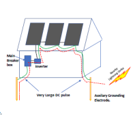
It is primarily the problem with a nearby lightning strike causing a very large spike on the grounding conductor.

1692466586753.png
(This is very similar to the image that Mike Holt shows)

I don't have a picture for a ground mount array, but the concept is the same. If there is a nearby lightning strike it can cause a huge voltage gradient across the ground. The path on the EGC between the two earth-ground points is very low resistance so there will can be a very large spike of current. Even if there is no arc from the EGC to something else, the pulse can damage equipment due to inductive or capacitive coupling.

The above was edited to remove the implied certainty of a large spike. The likelihood and magnitude of the spike is very dependent on many factors so saying there *will* be a spike is misleading.
 
Last edited:
It is primarily the problem with a nearby lightning strike causing a very large spike on the grounding conductor.

View attachment 163505
(This is very similar to the image that Mike Holt shows)

I don't have a picture for a ground mount array, but the concept is the same. If there is a nearby lightning strike it can cause a huge voltage gradient across the ground. The path on the EGC between the two earth-ground points is very low resistance so there will be a very large spike of current. Even if there is no arc from the EGC to something else, the pulse can damage equipment due to inductive or capacitive coupling.
BTW: The problem with the nearby lightning strike does not negate the need to tie the ground back to the house. Without tieing it back to the house, there is no ground fault protection.
 
Last edited:
It's not protecting the DC system. It's protecting people who may come into contact with the DC system.

There is no ground coming from the grid.
Only current carrying conductors.
The ground for your system is created in your service panel. (By the N/G bond)

It requires that it is to be connected to your grounding system. Which begins at your service panel.
It doesn't have to go directly to the service panel. It can run to your equipment, that is also connected to the grounding system.
No, that is not correct.
The provision you are looking at accommodates glass-glass frameless panels without a ground. Once you have metal parts on the panel you need a ground per 690.43.
No, not correct. 690.47A1 states the PV output circuit EGC is the only connection for ground required for the PV System. 690.47B allows you to add a ground
Then you may want to spend some quality time listening to Mike Holt's video's explaining exactly why you should do what you are not a fan of. But maybe all that research by all the NEC geeks is all BS. I dunno, but I kind of lean towards accepting the recommendations of the electrical engineers that come up with this stuff.
Mike Holt clearly says in his video that 690.47A1 is the only requirement for grounding. The AC output EGC is the only connection for ground required for the PV system.
 
No, that is not correct.

No, not correct. 690.47A1 states the PV output circuit EGC is the only connection for ground required for the PV System. 690.47B allows you to add a ground

Mike Holt clearly says in his video that 690.47A1 is the only requirement for grounding. The AC output EGC is the only connection for ground required for the PV system.

What about for non-isolated DC arrays? I can’t really imagine that the AC output EGC rule (if true) applied equally to isolated and non isolated topologies.

Also the EGC for the PV needs to go back to the AIO, SCC, or hybrid so the GFP can work correctly. Which may well force bond to the AC ground depending on how things are done in that box
 
690.47A

Information note points out that the inverter EGC is a common and accepted way to ground the array.

You can interpret (1) as relaxing the requirement (in earlier iterations) that the array must be grounded with a GEC (sized appropriately) instead of piggybacking on a EGC (which simplifies installation)
  1. For PV systems that are not solidly grounded, the equipment groundingconductor for the output of the PV system, where connected to associated distribution equipment connected to a grounding electrode system, shall be permitted to be the only connection to ground for the system.
  2. For solidly grounded PV systems, as permitted in 690.41(A)(5), the grounded conductor shall be connected to a grounding electrode system by means of a grounding electrode conductor sized in accordance with 250.166.
Informational Note: Most PV systems are functionally grounded systems rather than solidly grounded systems as defined in this Code. For functionally grounded PV systems with an interactive inverteroutput, the ac equipment groundingconductor is connected to associated grounded ac distribution equipment. This connection is most often the connection to ground for ground-fault protection and equipment grounding of the PV array.
 
Another thing I hope we can all agree on is that it’s better to run the EGC back now from the array to the SCC or inverter location (even if there turns out to be some combination of system types that may or may not require bonding to the EGC for the 120/240 system). Because that would be future proofed against changing system types or misunderstanding how to do this.
 
Always ground electric equipment but the question is where.
That's easy.
Since your ground originates at your N/G bond.
The problem is that people confuse ground with earth. Understandable, because we also call the earth "ground". As in "the man was standing outside on the ground".
But that's not the "Electrical Ground". Which is what we are discussing.
An EGC serves no purpose if it's not electrically grounded.
 
I thought the main point of Mike Holt's video was that code allows for a non connected auxiliary grounding electrode, which he was saying was a bad idea. If not, I should probably watch it again.

Not an issue for me, I ran back to my one and only EGC.
Code allows you to install an auxiliary ground rod. But it's not recommended.
But if an auxiliary ground rod is installed, it must be connected to the grounding system.
 
Again I’m not against it, I’ll be bonding mine to my main panel. The arguments for needing it just seem rather unlikely. I’m sure there are more convincing ones, but personally the lightning one seems outlandish.

A ground array is by definition grounded, to what degree can be argued no doubt. But I’ve seen lightning bolts blow though 100 foot tall trees, they’re not exactly worried about conductivity. I also think it’s a bit foolish to think a 6-12awg conductor is somehow harnessing that power lol
It has nothing to do with lighting. Lighting protection is a completely different system.
This is electrical grounding. For personal protection against shock. A lot of the high frequency AIO's have AC voltage on the PV circuit. (Along with the DC)
Which can be induced onto the frames of the panels. (If ungrounded)
But if a panel faults to the frame. That's a direct connection to the AC voltage. If the frame is grounded, when the fault occurs. The source of the AC will be turned off. By the protection of that circuit. (Breaker or fuse)
And make it safe, before anyone can get hurt.
The whole purpose of electrical grounding, is to clear faults. Before anyone gets hurt.
 
Would separate grounding systems be acceptable for transformer isolated SCC or inverter? IE no bonding between EGC to arrays and EGC for equipment inside the residence.

IE the inverter or DC DC converter employs a transistor and consequently has no galvanic path between the 120/240 system and the DC+/- from the panels.
 
One grounding system for everything.
Unless it's a separate dedicated system for separate loads. Then it creates it's own grounding with its own N/G bond.
But I would still connect to the existing grounding system. Because everything that you can touch, should be safe from all sources.
 
Doesn’t the transformer isolated power topology substantially cut the risk of the PV riding on AC that you get in transformerless? And the transformer provides an extra measure of isolation against some kinds of faults.

You would not be required to connect the EGC/GEC in a separately derived AC system (I think the most common way to form that is with an isolation transformer; I imagine if the separately derived system is in the same building it would be more cost effecting to reuse the same grounding system).
 
You would not be required to connect the EGC/GEC in a separately derived AC system
You would, if it serves loads in the same building.
Separately derived only refers to the neutral. Whether it's common between the two sources or not.
But the grounding is always tied together.
 
In that case that implies even an isolated PV system will with high probability trigger a need to bond the EGCs with the AC system of the building if it ever gets close enough.

For instance suppose you have an isolated topology inverter, and both AC and DC terminate in the same built in wiring area. Would the EGCs be obligated to be tied together since there are splices being made in one junction box?
 
Would separate grounding systems be acceptable for transformer isolated SCC or inverter? IE no bonding between EGC to arrays and EGC for equipment inside the residence.

IE the inverter or DC DC converter employs a transistor and consequently has no galvanic path between the 120/240 system and the DC+/- from the panels.
How would you isolate the SCC with a transformer? That is a big part of the problem. In the "olden days" you would have an input isolation transformer => Rectifier, DC Bus, Inverter => output isolation transformer; that provides a truly isolated DC bus. The input isolation transformer might have a high-impedance ground for sensing ground fault, but that wasn't very common. The problem with that scenario is that you have an additional 5-10% losses compared to a modern design.

So, yes it can be done... but it is expensive and non-constructive.

(I fought long and hard against losing the galvanic isolation back in the day because of how many esoteric problems it solved in general. But the reality is that the efficiency and reduced cost are worth a lot more. The NEC adapted as well, forcing center-point grounding as the default. The current approach really is the most practical solution though, which is why those of us who have been around understand and go with it... at least now.)
 
How would you isolate the SCC with a transformer? That is a big part of the problem. In the "olden days" you would have an input isolation transformer => Rectifier, DC Bus, Inverter => output isolation transformer; that provides a truly isolated DC bus. The input isolation transformer might have a high-impedance ground for sensing ground fault, but that wasn't very common. The problem with that scenario is that you have an additional 5-10% losses compared to a modern design.

So, yes it can be done... but it is expensive and non-constructive.

I was assuming use an isolated Buck/Boost (as appropriate) topology on the DC side. I don't think there's a benefit, I was mostly theorycrafting as to whether the old school way of doing things would allow different grounding approach vs the most common systems today (transformerless ungrounded PV) by reducing some of the risks. Not even clear that the one risk I thought is slightly improved (the large AC ripple on PV conductors, and I guess probably also higher PV voltage relative to ground) is worth the trouble relative to the hardware and efficiency cost.
 
I was assuming use an isolated Buck/Boost (as appropriate) topology on the DC side. I don't think there's a benefit, I was mostly theorycrafting as to whether the old school way of doing things would allow different grounding approach vs the most common systems today (transformerless ungrounded PV) by reducing some of the risks. Not even clear that the one risk I thought is slightly improved (the large AC ripple on PV conductors, and I guess probably also higher PV voltage relative to ground) is worth the trouble relative to the hardware and efficiency cost.
Ultimately you need to isolate the AC on input and output to make it work. Using power electronics you are always going to have capacitive or inductive coupling to some form of ground.

If you want an ungrounded system, the way to do it is frameless glass panels.
 
Another thing I hope we can all agree on is that it’s better to run the EGC back now from the array to the SCC or inverter location (even if there turns out to be some combination of system types that may or may not require bonding to the EGC for the 120/240 system). Because that would be future proofed against changing system types or misunderstanding how to do
Code allows you to install an auxiliary ground rod. But it's not recommended.
But if an auxiliary ground rod is installed, it must be connected to the grounding system.
You are mixing up GEC and EGC all over the place. I suggest you spend more time understanding 250 before you try to understand why you are incorrect.

Also, read the FPN in 690.47.
I think there is more to this story. The original question was about grounding his system that has a ground mount. So looking at the 2020 NEC, Article 250, Part VIII. Direct Current Systems applies. In 250.160 General it states that DC systems shall comply with part VIII and other sections of Article 250 not specifically intended for AC systems. So #1, whatever is intended only for an AC system does not apply to the ground mounted DC array. #2, 250.162 DC Circuits and Systems to be grounded. DC circuits and systems shall be grounded as provided for in 259.162(A) and (B). 250.164 Point of Connection for DC Systems is divided between off premises or on premises sources. An off premises source shall not be made at any point on the premises wiring. Is a ground mounted array considered off premises? I’m not questioning anyone’s expertise, experience or knowledge. I thought I would share this information. If I had my inspector hat on, I would say a ground mounted array is off premises and roof mounted would be on premises. Just my thoughts.
 
Even if you consider the ground mounted array off premises (I would). The wiring usually enters the premises. (That's where the loads are)
Therefore an on premises fault can travel to the array.
This is why we ground things. To protect people from faults.
If the entire system was off premises, then it wouldn't need to be connected to the premises in any way.
An example would be a solar farm located on a private property. (Land rented by the solar farm owner)
 
It's not protecting the DC system. It's protecting people who may come into contact with the DC system.

There is no ground coming from the grid.
Only current carrying conductors.
The ground for your system is created in your service panel. (By the N/G bond)

It requires that it is to be connected to your grounding system. Which begins at your service panel.
It doesn't have to go directly to the service panel. It can run to your equipment, that is also connected to the grounding system.
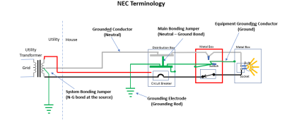
The Neutral coming from the Grid is called the grounded conductor in the NEC (it is grounded from the transformer to a grounding electrode) and is the main part of the grounding system for the main service panel. This is the reason that neutrals and grounds are bonded in the main panel.
 
The Neutral coming from the Grid is called the grounded conductor in the NEC (it is grounded from the transformer to a grounding electrode)...
No, the neutral is not grounded at the utility transformer (in the US). It is not called a grounded conductor until after the neutral-ground bond point.
 
No, the neutral is not grounded at the utility transformer (in the US). It is not called a grounded conductor until after the neutral-ground bond point.
Actually, Neutral is grounded at the utility transformer in the US. The bond is called the SYSTEM Bonding Jumper. However, in the US the utility does not provide a dedicated ground wire. Consequently, the bond has to be re-established on the customer premise in order to ensure a low-impedance fault path for clearing faults. This is done at the first means of disconnect and is called the MAIN bonding jumper.

1693161358573.png
 
Actually, Neutral is grounded at the utility transformer in the US. The bond is called the SYSTEM Bonding Jumper. However, in the US the utility does not provide a dedicated ground wire. Consequently, the bond has to be re-established on the customer premise in order to ensure a low-impedance fault path for clearing faults. This is done at the first means of disconnect and is called the MAIN bonding jumper.

View attachment 164756
BTW: This *does* kind of violate the golden rule of one and only one NG bond. However, the path for the undesired current is through the earth, not through an Equipment Grounding Conductor.
 

diy solar

diy solar
Back
Top