diy solar

diy solar

Converting hydro output to battery bank

Generally speaking, a higher flow will result in lower pressure at the nozzle due to pipe loss in the Weir.
Just like a solar panel, a turbine has a maximum power point. You want to first find the maximum power point by adjusting the flow. As the flow increases, the power output increases but the water pressure decreases due to the flow through the weir. At some point, the pressure gets so low that the power starts decreasing.

Once you have the flow rate dialed in, the charge controller can fine-tune by adjusting the output current till it finds the MPP. This is where a controller with hydro curves for its MPPT algorithm comes into play. A typical dollar MPPT has a very fast search algorithm that is designed for a typical solar I-V curve. A water turbine usually needs a slower search algorithm with a turbine curve.

I tried a Victron MPPT on my 24V turbine and it made no difference compared to the old 'dumb' C35 I had before. I never spent the money on a controller that could do a Hydro curve so I don't know if it would have improved the output or not.
 
Lost pressure due to higher flow had better not be significant. If it is, pipe is too small.
Pressure at the nozzle makes velocity, and turbine speed needs to drop water velocity near zero to extract all the energy.
Normally done by winding alternator for a given head and voltage. Controllable field winding would accomplish same, has efficiency loss compared to permanent magnet. Switcher (e.g. MPPT) could electronically match generation to battery voltage.
 
I am not sure how that would work. It would need to adjust the flow based on the battery SOC.

PWM. Open a dump valve, or cut off water to turbine, when battery voltage hits target.

Diverter at nozzle could also do it. I understand large turbines deal with sudden load dump by turning nozzle away.
Small system, maybe open a solenoid valve to dump excess. Avoids water hammer compared to shutting off flow, but wastes water.

Can't do good linear control with a valve, that wastes power dropping pressure across valve.
Ideally would have an adjustable orifice nozzle, allowing water to back up in reservoir.
Maybe a needle motored into center of nozzle.
Multiple nozzles, turn each on/off to vary flow. Several diameters and it would be like a binary code.
Seems overly complicated compared to a dump load with a pwm controller.
 
It may be.
With limited water source, would like to use reservoir as battery, not waste it.
But the commodity lithium batteries are probably cost-competitive.

Unless open-circuit voltage is within BMS tolerance, I think you want redundant protection. I could imagine PWM dump load failing open.
Maybe over-voltage detection to remote trip breaker. Or to shorting relay, but that would likely cycle on and off. Bistable relay?
 
Is it all on your property? Back up water onto someone's property? Run of river (down stream rights)?

It’s mostly all on my property. A spring that naturally flows, the rest comes from a little lake further above that’s fed by another spring that drains down on my property.
 
I’ve checked into the watter buddy before. Not sure if it’s how the alternator is designed, but I could only produce roughly 9 watts with the approximate 30 psi and (1) 4mm nozzle @ 4gpm.

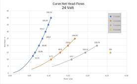
This other system I’ve shared is capable of producing 248 watts with my head and flow rate of 2.77gpm.

Hydraulics is not my weakness as I drill oil wells and deal with this all the time. My weakness is this electrical stuff.

I see the penstock as nothing more than a drill stem and the nozzles relative to how we jet drill bits.

And yes, 3-4” penstock is what I’d use given to flow capacity.

Here’s a daily calculation I use and will share to calculate head pressure.

Height in feet x weight of water x constant
in my case:

77’ drop x 8.33 or 8.34 x .052

33.35 psi.

Since we use drilling fluid and not only water and seawater, pressures can get high very quick. For example. At 20,000’ tvd (vertical depth), using a 14.8 peg drilling fluid will yield 15,392 psi. High pressures.
 
It’s mostly all on my property. A spring that naturally flows, the rest comes from a little lake further above that’s fed by another spring that drains down on my property.
BTW: Make sure you understand the water use rules in your location. There are horror stories of people putting systems on their own property and then the government dropping a huge fine on them for not having the right permits.

I forget the name of it now, but there was a water bill passed by Congress that put nearly every puddle in the nation under federal control. Even land that had no water on it but was part of a watershed could be controlled. I recently heard a court took some of the teeth out of the bill....but you should check.

When I put my system in (In Montana), there were 3 or four forms to fill out and they were easily approved... I probably could have got away without it but I did not want to take a chance.
 
Lost pressure due to higher flow had better not be significant. If it is, pipe is too small.
Pressure at the nozzle makes velocity, and turbine speed needs to drop water velocity near zero to extract all the energy.
Normally done by winding alternator for a given head and voltage. Controllable field winding would accomplish same, has efficiency loss compared to permanent magnet. Switcher (e.g. MPPT) could electronically match generation to battery voltage.
Pipe loss is real and should be accounted for. Of course, you can lower pipe loss with larger pipes, but it is just like wiring. At some point making it larger is just not worth the gain. Even if the pipe loss is zero, you need to find the right Pmax combination of pressure and flow. At some point, the additional flow will not create more power and it is just wasting water. In fact, if the turbine housing cant drain the excess water, it will cause turbulence and reduce the power output.
 
If you click on the picture, it’ll give head on the left. Attached is a pic
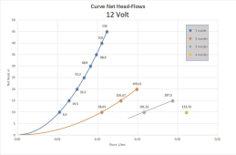
Ah, I didn't click.

Both graphs go to only 45' head. Maybe it can handle the higher RPM of your 77', maybe not.
If it does, I would expect 48V could be within range. Higher frequency operation, which should mean the magnetic components can handle more voltage (polarity reversal of AC occurs more often, less current than same voltage at lower frequency, avoids magnetic saturation.)

Worth considering.

1689532951787.png

1689533046982.png
 
It may be.
With limited water source, would like to use reservoir as battery, not waste it.
But the commodity lithium batteries are probably cost-competitive.
My impression from the description is that the catchment at the top of the weir is not going to be large. Consequently, anything that is not going into the penstock is going to go down the stream. (It will be 'wasted' anyway).
Unless open-circuit voltage is within BMS tolerance, I think you want redundant protection. I could imagine PWM dump load failing open.
Maybe over-voltage detection to remote trip breaker. Or to shorting relay, but that would likely cycle on and off. Bistable relay?
I see your point. It all comes down to how much you want to pay for the insurance.
The good news is that if you are doing it as a back-up it can be a simple on-off valve at the turbine and you don't have to run controls all the way up to the penstock.
 
My impression from the description is that the catchment at the top of the weir is not going to be large. Consequently, anything that is not going into the penstock is going to go down the stream. (It will be 'wasted' anyway).

Variable water flow, I understood.
If system undersized, you waste a lot of available power.
If oversized, air fills the tube, turbine runs under reduced pressure and sees surges.
I think two nozzles (two pairs), one undersized and one oversized, could cover a wide range by very low frequency PWM of a control valve for the oversized nozzles, controlled by a float switch.
 
I ended up with this as a dump load:

1689538925698.png

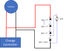
  • Pick a power (Pz) that is a bit higher than Pmax of the turbine. PZ should be equal or less than the sum of the power ratings of the Zenor diodes should be. (Pz > Pz1 + Pz2 + Pz3 + ... Pzn). If the actual output of the installed system is less than the rated power of the turbine, you can use a lower value for Pz.

  • Pick a voltage (Vz) that is below the Vmax of the charge controller but larger than Vmax when the batteries are charging. This is what the sum of the trigger voltage of the zenor diodes should be. (I had a 75V charge controller on a 24V system so I used something like 35v. This is well above any normal operating voltage while charging and well below the max voltage of the Turbine.

  • The current max current will be Pz/Vz. (It will actually be less than this because Vz is off the Pmax point of the system so the actual power produced will be less)

  • The power Zenor diodes should be mounted on good heat syncs.

  • The fan is a 12V case fan that only runs when the Zenors start conducting. It should be ducted over the heat sinks of the Zenor Diodes.

200W is about the max power that this could be used for in any practical sense.

Surprisingly, the heat sinks were going to be the major cost till I found a big-ass multi-component heat sink at a local electrical surplus store for ~$20.

Zenor diodes don't have a knife-edge voltage where they start conducting They have a range of voltage between off and full on. Consequently, the turn-on transition was rather gentle.

This is wasting the excess energy, but it was a cheap and simple solution. In my case, trying to use the excess energy for something like water heating was not worth the effort.
 
Make sure you understand the water use rules in your location. There are horror stories of people putting systems on their own property and then the government dropping a huge fine on them for not having the right permits.
This is all in Central America. Anything goes. Only thing that could happen is the neighbor above block that overflow off of his little lake
 
I would expect plastic nozzles and wheel to be short lived compared to copper/brass/bronze.
Yes, I’ve considered this several times. If this 248 watts is true with my setup, then there’s nothing else like it, American or Chinese made. I’m sure I could swap the plastic pelton for something more durable.

Just so everyone knows, it’s not that I’m trying to go cheap. I called Langston and basically put, I have good head, but not enough flow. Otherwise, I checked power spout, Langston, watter buddy, and everything in between. Plus if it doesn’t work out, I’ve only lost out on maybe $1000. The charge controller and other items can be used for potential wind or more pv panels.
 
Back
Top