diy solar

diy solar

Dongguan Lighting: Purchase 280AH LiFePo4 cells. Purchase & Review

If the curve is flat why does it make a difference? Voltage is voltage. What is the advantage of equalizing the voltage at the top, versus the middle or bottom?

Because even though they are at the same voltage, they are not at the same state of charge. If both cells are at say 3.2V, but one is at a lower state of charge, the BMS will cut off charging once one cell reaches e.g. 100% at 3.65V while the other one is not yet there and could be 20% lower - which will also mean the BMS will cut off the battery during discharge faster than the actual capacity.

You can only have a clear picture of the state of charge based on voltage at very low state of charge (bottom balancing) or very high state of charge (top balancing).

charge.jpg


Think about it, when you have one cell at 45% and the other at 25%, there is almost no voltage difference, but 20% capacity difference. You only see a noticeable voltage difference at high or low states of charge: that's where you balance.
 
Last edited:
That is a great explanation. The graph helps. I could not find that in the Wiki. If I understand what you are saying, it depends on your application whether it is best to equalize the cells at the top or the bottom. I kept hearing from the EV conversion community that bottom balancing was the best. Many of them did not use BMSs. Since I use a BMS I just thought putting cells in parallel would equalize them.
I see from the graphic that where the curve has some slope to it one has more precision in getting to the same SOC. If the cells are of slightly different capacity you can never change that and they will never be balanced in terms of capacity.
I can understand why in a stationary application like storage you would want to balance SOC at the top. That is where storage applications spend most of their time.
 
When you're at 3.2V, you can essentially go constant voltage........

The way I do it: either each cell is individually charged with a CC/CV capable power supply to 3.5V to 3.65V depending on your preferred state of charge,
What happens if you go to the CV stage at 3.2? I understand 3.5 or 3.65 are closer to the top. Or is it a coincidence that on a ten keypad that 2 is just below the 5? ;)
 
I'll write this up and add it to the Wiki.

If you go CV with 3.2V and wait until the current drops to 0, you might have to wait quite a while since the battery will keep absorbing energy (I'll record that out once I have my new cells, never checked that). See the graph below:

qidwvcdb3z4i.jpg


From this graph you can see that you can reach 95% state of charge at 3.4V if you charge slow enough. 3.2V might actually be too low and is probably still in constant current territory. I believe CC goes until 60% state of charge, which would be around 3.35 or thereabouts, so my 3.2V I mentioned before was too low. And as mentioned, at 3.4V you can reach 95% with CV mode.
 
That is another good explanation about why one might choose a slightly different constant voltage point depending on the c rate? I am just speculating.
 
3.35v at rest is 90%

At 0.1C rate naturally, it is lower charge state
At 0.2C even lower.

0.1 C rate of 456Ah, is roughly 45A Charging, 0.2C 90A
I already see huge difference between 10 and 40A charge.
(My situation now)

Difficult but interesting!

Mostly difficult to get the corresponding SOC of the measurements.

Many variables, C rating, temperature, maybe even SOC?
Does an "empty" cell absorb faster then 2/3 charged one??
I don't know.
With different resistance, it probably would be.
But I don't know if it has different resistance at various SOC.
 
That's why you charge an empty cell with constant current.

I already see huge difference between 10 and 40A charge.

But not regarding state of charge. In the graph, the battery is at 90% state of charge at both 3.39, 3.14 and 3.45V - it just depends on how fast the battery was charged. This is again an indicator that you should not rely on voltages to determine state of charge. Instead, if you put the cell voltage at 3.6V (check the graph) you can see the curve going flat until it reaches 100% state of charge. At this point, your current to the battery drops to 0 and you know for sure you're dealing with balanced cells, regardless of history.

Not 100% sure I understood your comment though - if I'm just repeating what you meant, apologies.
 
why one might choose a slightly different constant voltage point depending on the c rate?

It all depends on what you require from your battery. However I always make sure for solar applications to top balance at 100% (especially with cells I don't know the history of) with 3.6V (or 3.5 even and just give it a long time for the current to go to 0. Charge rates using solar are typically very low C rates in any case. So are most discharges, so they will keep in balance for a very long time if you do it properly at the beginning before pack assembly. Since we're dealing at low C rates, there is no need to balance at 0.5C with 3.65 (or even overcharge) voltage - it just doesn't match the usage graph for solar.
 
@upnorthandpersonal
The SOC of 2 cells, both 3.2 volt can have different SOC??
(Not a few% but significant difference?)

That is new for me.

I have new Eve cells, 152Ah, that came fresh from the seller.
Playing around with one costed me a replacement cell.

That's why I am not happy to top balance.

Bottom balance might be more logical option.
I have discharger for 150w, that can be used per individual cell

If what you say is true, a parallel set of 3 can have 3 different SOC between the 3 cells.

I read about people who say you should go down to 2.0 volt, and people who say you absolutely should not go below 2.5 volt.

The first group does say you should not leave them at 2.0v, but recharge them asap. A few days will damage

The second group more or less say the same, but leaving at 2.5 for a few days doesn't damage.

As both is possible, and there are watts between the both, neither of them is 0%

It's possible to discharge to 0 volt.
Then the SOC is indeed 0%

For lead acid, preparing the Epson salt method, draining the battery to 0 volt (I can get to 0.5v) the dead 200Ah gives below the 10.5 down to zero even more Ah then above 10.5 to 12.7v
Amazing 400 watt hours!

The "0% SOC of lead acid at 10.5v is not empty at all.

If I am to drain the cells, 2.5v is low enough? 2.0 is better?
Or can 2.8v be used as well?

The "Higher" charged the better for me.
Rain season is starting, I'm not able to recharge to full in one day.
Down to 2.5 might need a week or more to be able to reach the 3.4 volt region again
 
To do a proper balancing, you need to know what the state of charge is. You can't rely on just the voltage over the 'middle' of the graph (yes, two cells at 3.2V can have a different state of charge - check the graph - minimal voltage differences can be big SoC differences, and this is extremely difficult if not impossible to measure, especially with a run of the mill multi-meter because of potential other variables).

Since you don't have a record (by means of a coulomb counter for example) of a cell that comes from the factory, you can not know it's state of charge just by measuring the voltage (the cells come from the factory usually with a SoC of around 40% to 50%, recommended for shipping, but could be 30%), and the voltages can be too close to each other to accurately measure in the 'middle' of the graph.

Therefor, you can do two things: bottom balance by going towards the 0% SoC (you don't have to be at 0, you just need to be in the region of the graph that is highly non-flat) where the delta V becomes very obvious, or go towards the 100% state of charge where the delta V also becomes very obvious.

Bottom balancing is something you tend to do if your cells are in that region often (i.e., depleted battery pack) and top balancing is something you do if your batteries tend to be in that region, i.e., charged. Solar tends sits in the latter category where a pack is more often fully charged than fully discharged. Therefor we tend to use top balancing in solar applications.

It is impossible to destroy a cell using top balancing when you have a precise constant voltage power source set at or below 3.6V (or below, 3.65V if you're brave or want every last bit of power) and monitor the current going to 0 - as long as you are also within the CV region of the charge curve; before that use a lower voltage to make sure the current does not exceed the max. C rate (and use the current limiter on the power supply if you have one that can actually dump too much).

If you want to be extra cautious, you can even start setting your voltage at the current cell voltage, say 3.35V and wait until the current goes to 0, then increase the voltage slightly, and again wait for the current to go to 0 - always making sure you never ever go over 3.65 max (I use 3.60V max, the last bit is completely unnecessary to get out of the battery and gives no useful returns, but you could use it as a balancing point to reach 100%). Just never, ever, go above that unless you absolutely know what you're doing and are playing with overcharging etc. but as you can see from the second graph, it is absolutely not needed to ever go over that voltage.

You keep the power supply in CV mode and keep it at 3.6V until the current drops to 0; you do not put the power supply at 4V for that bit of extra power, see the voltage drop because the current it provides (under load), and then measure until the battery hits 3.6V. You will overshoot because that last bit goes really fast and then you're putting 4V on the battery and you will destroy it.

The first group does say you should not leave them at 2.0v, but recharge them asap. A few days will damage

The second group more or less say the same, but leaving at 2.5 for a few days doesn't damage.

As both is possible, and there are watts between the both, neither of them is 0%

The amount of power in the battery cell between 2.0V and 2.5V is negligible. The amount of power in a battery cell between 3V and 3.5V is over 90% (even 95%) of the cell. Just 0.5V difference between both.

Edit: let me put that last sentence in perspective: 0.5V over 90% of the capacity. That means that 10% difference in state of charge is given by 0.055V. If you have a 2 digit portable multi-meter (with it's own accuracy problems), in an uncontrolled environment, you'll never get even close to 10%, let alone better. This is why you want to be in a region of the graph where even large-ish changes in voltage are negligible for balancing.
 
Last edited:
To do a proper balancing, you need to know what the state of charge is. You can't rely on just the voltage over the 'middle' of the graph (yes, two cells at 3.2V can have a different state of charge - check the graph - minimal voltage differences can be big SoC differences, and this is extremely difficult if not impossible to measure, especially with a run of the mill multi-meter because of potential other variables).

Since you don't have a record (by means of a coulomb counter for example) of a cell that comes from the factory, you can not know it's state of charge just by measuring the voltage (the cells come from the factory usually with a SoC of around 40% to 50%, recommended for shipping, but could be 30%), and the voltages can be too close to each other to accurately measure in the 'middle' of the graph.

Therefor, you can do two things: bottom balance by going towards the 0% SoC (you don't have to be at 0, you just need to be in the region of the graph that is highly non-flat) where the delta V becomes very obvious, or go towards the 100% state of charge where the delta V also becomes very obvious.

Bottom balancing is something you tend to do if your cells are in that region often (i.e., depleted battery pack) and top balancing is something you do if your batteries tend to be in that region, i.e., charged. Solar tends sits in the latter category where a pack is more often fully charged than fully discharged. Therefor we tend to use top balancing in solar applications.

It is impossible to destroy a cell using top balancing when you have a precise constant voltage power source set at or below 3.6V (or below, 3.65V if you're brave or want every last bit of power) and monitor the current going to 0 - as long as you are also within the CV region of the charge curve; before that use a lower voltage to make sure the current does not exceed the max. C rate (and use the current limiter on the power supply if you have one that can actually dump too much).

If you want to be extra cautious, you can even start setting your voltage at the current cell voltage, say 3.35V and wait until the current goes to 0, then increase the voltage slightly, and again wait for the current to go to 0 - always making sure you never ever go over 3.65 max (I use 3.60V max, the last bit is completely unnecessary to get out of the battery and gives no useful returns, but you could use it as a balancing point to reach 100%). Just never, ever, go above that unless you absolutely know what you're doing and are playing with overcharging etc. but as you can see from the second graph, it is absolutely not needed to ever go over that voltage.

You keep the power supply in CV mode and keep it at 3.6V until the current drops to 0; you do not put the power supply at 4V for that bit of extra power, see the voltage drop because the current it provides (under load), and then measure until the battery hits 3.6V. You will overshoot because that last bit goes really fast and then you're putting 4V on the battery and you will destroy it.


The amount of power in the battery between 2.0V and 2.5V is negligible. The amount of power in a battery between 3V and 3.5V is over 90% (even 95%) of the pack. Just 0.5V difference between both.

Edit: let me put that last sentence in perspective: 0.5V over 90% of the capacity. That means that 10% difference in state of charge is given by 0.055V. If you have a 2 digit portable multi-meter (with it's own accuracy problems), in an uncontrolled environment, you'll never get even close to 10%, let alone better. This is why you want to be in a region of the graph where even large-ish changes in voltage are negligible for balancing.

You have a wealth of knowledge my friend, thank you for this very well written explanation!
 
Yes, I'm at 12 V packs. Four 280 Amp packs in parallel.
Okay, I misunderstood. I thought it was twelve 12 volt packs in parallel. I am still curious what your thought process was for doing four packs with separate BMSs instead of one big pack of 4 cells in parallel and then put each of those groups in series for one big pack. There is no right way, because each user has different needs and desires. Your answer would be informative for others.
 
Okay, I misunderstood. I thought it was twelve 12 volt packs in parallel. I am still curious what your thought process was for doing four packs with separate BMSs instead of one big pack of 4 cells in parallel and then put each of those groups in series for one big pack. There is no right way, because each user has different needs and desires. Your answer would be informative for others.

Can't speak for Kimmy, but some people prefer the 'series first' over 'parallel first' (i.e. 4S4P vs 4P4S / multiple battery packs connected in parallel vs one big battery pack with cells in parallel and a single BMS) for two reasons:
  1. True cell level monitoring/control
  2. Redundancy / compartmentalization
The downsides I see with this approach are added complexity, cost, and more potential points of failure.
 
Can't speak for Kimmy, but some people prefer the 'series first' over 'parallel first' (i.e. 4S4P vs 4P4S
Yes I understand. I think the answer that @Kimmy gives will be informative for others, whether it is personal preferences or unique characteristics of the motor coach.

Earlier I had a conversation with a member here who chose redundancy because that was a sailboat and additionally the smaller packs were easier to stow and secure in the hold of the sailboat.
 
@upnorthandpersonal

I have now 3 cells in parallel.

Even if I do top (or bottom) balancing as parallel set, there still might be a large difference between the 3?

Showing 2.5 volt don't have to be 2.5 volt?

One cell could be at 3volt, the other at 2..

To my understanding, if put in parallel, cells, batteries, no matter the chemistry, (e.g. lead acid or lifepo4 or lithium ion or... , Not mixed)
Parallel will balance the state of charge.

Preferably but not necessarily, they are the same size.

It can be a set build up by different AH, like 20, 50, 90, 150 and 280Ah.
This would make one "cell" (set) of 590Ah

Having different SOC will be equalised, like barrels of water, each with different capacity, but connected.

There might stay slightly different SOC, due to differences between the cells.
This can (most likely not) also happen with identical cells due to minor differences as no cell is exactly the same.

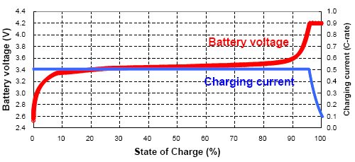
Putting 2 or more cells from totally different SOC in parallel is asking for "fireworks", the higher charged with charge the lower one at its C-rate.
(Probably higher, if you would make a short, the amps of 90Ah cell go close to 1850A).
Anyways, it charges the lower one, and the lower one discharge the higher SOC.
With bigger difference, your busbars and cells get warm (maybe even hot)
With huge difference...
I don't want to try :cool:


This is my knowledge I learned like "always" since I began playing around with rechargable Batteries.

If I have learned wrong, it's always good to learn new.

My accurate, or not so accurate 2 digit multimeter will atleast provide the same numbers. They might be "wrong", still the same.

One cell was on 3.30, not wiggle.
When I connected that one, it got warm for short time.
Not hot, but clearly doing something.

With now just 0.005 cell set difference at rest (after 10-15 minutes) (sometimes less) I would say that the method I used was really effective solution.

That they now have different voltage during charge, that is due to many variables, like the thickness of the busbars, screws used, maybe oxidation of the aluminium poles, etc etc etc.
And, it's not one long line, they are on top of eachother (in a rack), that's wires/cables between the layers, also have influence.

I'm gathering materials and equipment to melt my copper and make my own busbars for 5 cells in parallel.
(I've ordered 2 x 120Ah extra, 32*)
Sadly the 152Ah is no longer available.
Otherwise I would have chosen them.
The 120Ah from the same factory has the same housing, exactly the same size.
Being from the same factory and same size the pouches (if sealed) or layers will be the same. (Same internal resistance)
Weight is naturally different.

20A induction heating
And 40*60mm crucibe

Clay and sand make perfect molds.

With my new busbars, I'm sure the cell set difference will be as low as possible.

If you are sure that it is likely that my individual cells are out of balance, the only way to get them in balance is to lower the voltage as much as possible
(Till one set of the 16 reach 2.5v)
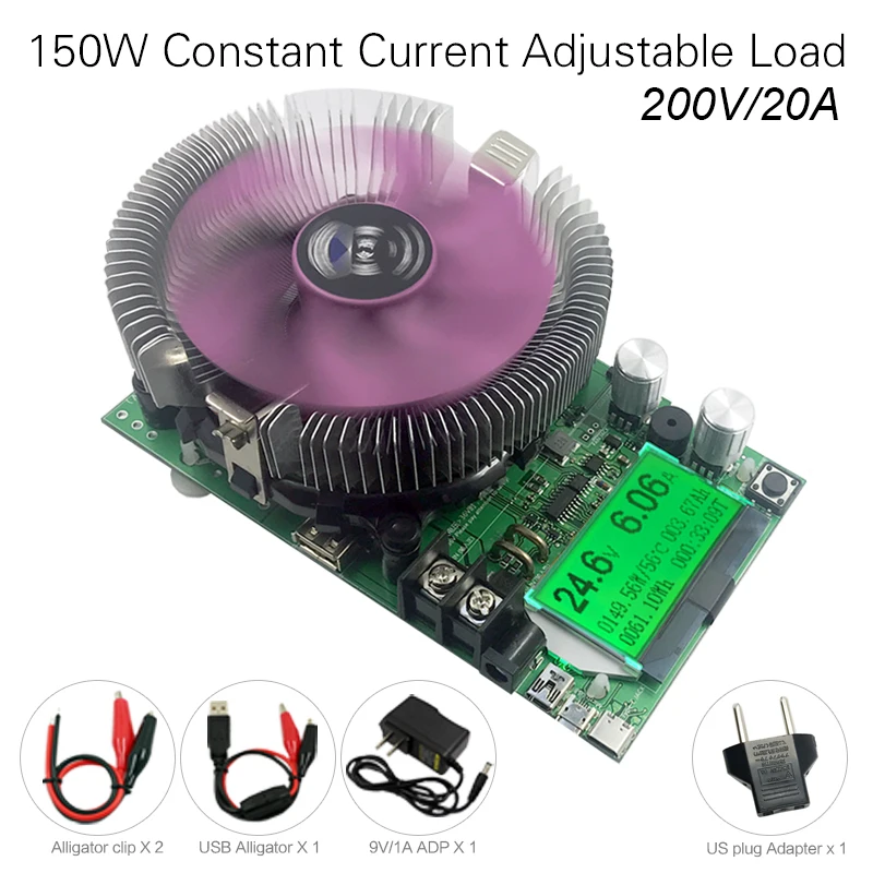
Disconnect all cells, and use the discharger
To get all individual cells down to 2.50
(Discharger have also 2 digits)

They are supposed to be close to eachother, it should not take long for each cell to reach 2.50 volt.

48 X "not long" still is several hours..

Then re-asemble the parallel and series, and start charging.

In my situation I need sunlight to do this.

I have 27*330 watt panels, they can produce enough for our household.
At the moment I'm limited to max 4500watt charge, say 50A.
(We also use electricity)
(We removed the dead 16* 200Ah lead acid and their rack. The amount of space was enormous, so we decided to use this extra space for our bedroom and took down the wall.
As result, nothing is where it is going to be, output and usage is temporary limited till construction is finished.
It will be a nice sounds proof closet that holds the 3* MPPT Inverters, batteries, my network equipment and 2 NAS + 2 mining rigs for crypto.
Naturally with enough air ventilation and cool, filtered air from our (air-conditioned) bedroom.
This cool air is needed as we have regularly +40 degrees Celcius outside in the shade.
The mining rigs I have left over, and can make about 4 USD per day.
They are paid for, high end GPU, so..
If electricity is free, why not? :) )
They make / mine (calculate) $120 each month, but use about 750w 24/7
(= The 32*120Ah extra)
 
Why don't you try some premium battery from China, pls check my post:


And for datasheet of CATL LFP 280Ah, pls check:

 
I have now 3 cells in parallel.
Even if I do top (or bottom) balancing as parallel set, there still might be a large difference between the 3?
Showing 2.5 volt don't have to be 2.5 volt?
One cell could be at 3volt, the other at 2..
All the cells will have the same voltage, but not the same state of charge because each cell may have a slightly different SOC. If you are talking about the proposal you were going to have with new cells with a different capacity then that enters the equation.
To my understanding, if put in parallel, cells, batteries, no matter the chemistry, (e.g. lead acid or lifepo4 or lithium ion or... , Not mixed)
Parallel will balance the state of charge.
Only if you charge them close to the knee of the curve at 3.65 volts. Since you have been talking about mixing different capacity prismatics I think the only thing you can be sure of is each group of parallel cells will be at the same SOC of other groups if you parallel them and charge them to 3.65 v. Then they will be equal voltage.
Preferably but not necessarily, they are the same size.

It can be a set build up by different AH, like 20, 50, 90, 150 and 280Ah.
This would make one "cell" (set) of 590Ah

Having different SOC will be equalised, like barrels of water, each with different capacity, but connected..........
That analogy works as long has each barrel has verticle sides. If the shape of the barrels are different one might have 25% and the other might be at 27% but the pressure (voltage) will be the same. As they empty water will flow between the barrels like eddy currents between the cells.
 
You can get all three parallel cells at the same state of charge by getting them to 3.6 volt-ish, and let the current go to 0.

Is this really necessary on these? Doesn't your BMS take care of a lot of it? Forgive me if I'm ignorant of this stuff. My batteries came all within .003 volts from the factory. What am I missing here?

You BMS does not take care of a lot of this. Your BMS should be considered as a protection device for when things go very wrong, and it may help keep cells balanced in certain conditions. It does not initially balance the cells for you - that's up to you to do by (easiest way) putting them all in parallel and get them to 3.6V and watch the current go to 0.

Of course, it might be that your cells are already balanced, or that for your application it does not matter. I'm also not telling anyone they should do what I say or their batteries will go bad. I'm just saying that, from experience, you do not trust cells that come from the factory or seller to be balanced but they should be before placed in a pack.

Parallel will balance the state of charge.

If you have a battery that is at 3.35V and another at 3.4V - that's 0.05V difference. This could be 20% or more of your total capacity difference. How many amps are going to flow in this set-up? We're talking milliamps. How long to balance 28Ah (just 10% of a 280Ah battery)? Keep in mind that when they are at 0.025V difference, this current becomes even less but could still be 5% or more of the total capacity off balance. This is like balancing your two water barrels with an eyedropper.

The reason this works with other chemistries like lead acid is because the voltage curve is not flat like on LiFePO4. You need a voltage difference to balance, which is why you do it for LiFePO4 on the top or at the bottom.
 
Getting just 3 parallel cells to 3.6, that will be challenging, without lifepo4 Charger.
All S16 , 3 parallel to 3.6,(or 2.5) might be an option.

During charge, it seems to hang at 3.35v, for long time, the flat curve.

When it pass this point, the rest go relative fast.

As I already fried one cell, I'm little anxious to go over the 3.4v
That's why I set it to 3.4375, or 55v.

When my new 400A smart Daly arrives, I might get more insight and more confident to go higher
 
Getting just 3 parallel cells to 3.6, that will be challenging, without lifepo4 Charger.
All S16 , 3 parallel to 3.6,(or 2.5) might be an option.

During charge, it seems to hang at 3.35v, for long time, the flat curve.

When it pass this point, the rest go relative fast.

As I already fried one cell, I'm little anxious to go over the 3.4v
That's why I set it to 3.4375, or 55v.

This is why you use a constant voltage power supply. You disconnect it, set it to 3.5V (for example, or less to give it a try), then connect it. That way you make sure you never go higher than 3.5V and the current will go to zero near the end of the charging. Do not set the voltage by measuring under load (i.e., when the supply is connected to the cell or when you don't have a true constant voltage supply) - that is the wrong way to do it and will lead to damaged cells.
 
@fhorst ,
You are trying an experiment by mixing cells of different capacity. Earlier we discussed some reasons why this might work but those were only calculated guesses. If you do this, I think it is important to eliminate any variable that might ruin this experiment. That is why I think you should parallel all your cells together and charge them all to 3.6 volts. I realize that will be a lot of work and require you to take youre existing pack apart to do that.
What @upnorthandpersonal said is important because you have to set your voltage source to 3.6 volts before you connect it to the cells because that is the only way you know it is correct.

I would also suggest you start a new thread so this experiment can be easier for others to find with search engines. That way it will help others.
 
Would love to be able to source four of these cells and a BMS from a stateside vendor to put together a battery for a camper I just bought. New to this sandbox, but not electronics. Am I wrong in thinking I can make a safe alternative to a battleborn battery that is nearly three times as capable for less than the cost of one of those batteries?
 
............ Am I wrong in thinking I can make a safe alternative to a battleborn battery that is nearly three times as capable for less than the cost of one of those batteries?
You are correct in thinking that you could do it for $800 to $900 if you were to buy the batteries from China. Approximately $600 for batteries, $120 for BMS and $80 to $180 for other parts and tools. Compared to the 100 Ahr BattleBorn you would have a 280 Ahr DIY 12 volt battery. I do not know the market details of why these cells are so inexpensive. If it were a sustainable or consistent source of supply someone could take a risk and stock up on these and start a small business selling cells or 12 volt drop in replacements.
 
On this thread there is a guy selling 105 Ahr cells. That would be a $500 to $600 BattleBorn subsitute:

 
This is why you use a constant voltage power supply. You disconnect it, set it to 3.5V (for example, or less to give it a try), then connect it. That way you make sure you never go higher than 3.5V and the current will go to zero near the end of the charging. Do not set the voltage by measuring under load (i.e., when the supply is connected to the cell or when you don't have a true constant voltage supply) - that is the wrong way to do it and will lead to damaged cells.
I have 32 of the 280aH cells set to arrive any day now. I will be making x4 24v 280aH batteries with them. I have been planning on parallel balancing them in sets of 8 for as long as it takes, but they sent me a video before shipment showing all the cells reading 3.28/ea. One seemed to bounce between 3.28 and 3.29...but the point is, I've been hoping and expecting them to arrive in close voltages.
I've been hoping that once they were parallel balanced in sets of eight I could series connect them, screw on a fuse block and connect them each to my MPPT All-in-one 80a SCC and my 2.25kwh array and charge them to 28.8v. All that to say this: Are you saying that would be bad, that I can't charge them initially this way?
 

diy solar

diy solar
Back
Top