wpns
Solar Joules are catch and release
What's the minimum resistance that the RSD sense circuit in the 18Kpv will detect as a closed circuit? I'm using 75-100 feet of CAT6 cable (only one pair), and the total resistance is around 5 ohms, which makes the inverter think the RSD switch is open.
I'm currently working on using all four pairs to drop the resistance a lot, but if 1 ohm is right on the borderline then I probably want to add a small relay or SSR or something...
Thanks!
I'm currently working on using all four pairs to drop the resistance a lot, but if 1 ohm is right on the borderline then I probably want to add a small relay or SSR or something...
Thanks!


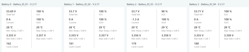
 Mostly just wondering if I should be concerned, but 50mV delta within a battery is OK?