Zwy
Solar Wizard
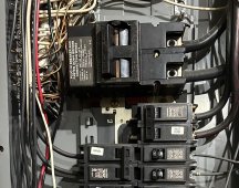
I looked at the price I paid as insurance down the road. I work away from the shop during the summer and if the wife called and said the inverters aren't working, she can throw the 3 pole. This would keep power to both freezers and refrigerator. I stock a side of beef every year, the transfer switch is cheap insurance.