energyhunter
New Member
- Joined
- Feb 20, 2022
- Messages
- 83
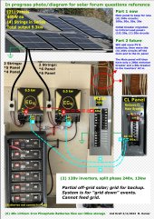
This photo diagram, DRAFT 2, covers my installation nearing completion. Yes, exposed wiring will be in conduits.
Question 1
Since the Critical Loads (CL) panel will eventually hold ALL of the circuits currently on my main, shouldn't I just leave the 200 amp entrance breaker that came with the CL panel? I am concerned the 60a breaker feeding the CL will not be adequate once all circuits are put on the CL
Question 2
Keeping in mind that this is not a grid-tied nor a mobile system, should the NG bonding screws be removed from BOTH inverters?
(Inverters were shipped on May 27, 2022)
Thanks to previous replies from PreppenWolf, Gavin Stone, dcg9381, Mattb4, Zwy, NEpowerandlight and others; I value highly your insights and advice.

")