diy solar

diy solar

EG4 Chargeverter

Yeah, that's what I generally believe. Maybe Texans just don't believe it ever gets colder than 14F on earth.
I have been known to tell people visiting Texas that the climate is a lot different here. In fact, water freezes here around 40 degrees, which is why it feels so cold when it's below 40. Amazing and scary how many people over the years have responded, "Really?"
 
Did you manage to get a shipping estimate from SS to UK? This looks a nice charger, my diesel geni is a little too dirty for my liking. Worst case to DIY one its only a couple telecoms power supplies, but would need some CANBUS and coding for the voltage and current control I think.
I didn't unfortunately, SS never replied to me. So I changed tack and went with Eltek Flatpacks instead; as you say they're CANBUS controlled, its a project I have sat on my desk for a rainy day :)
 
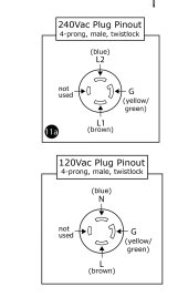
yes, 240v mode uses L1, L2 and ground

TT-30 P 120v plug needs to have neutral go to L1, L go to L2 and ground to ground
i read that as “connect brown wire to neutral pin” as the brown wire is L1 according to the factory pin out in the manual.

but the manual shows both the L5, and TT has the blue wire connect to the neutral pin.

In 120 mode is the neutral blue, or brown?

I know someone posted elsewhere in this thread that it doesn’t matter. Neutral matters or we wouldn’t have polarized plugs.

or does neutral not matter in this specific situation because of the auto sense operation of the chargeverter?

This, pretty sure.

Neutral matters for polarized plugs for safety reasons, but not so much equipment function.
 
Both wires of the CV are already sufficiently isolated for 120V relative to ground. The CV only cares what voltage it has across it. Therefore it doesn't matter which leg is now held to ground potential as neutral, as either leg is safe to be the 120V side.
 
This, pretty sure.

Neutral matters for polarized plugs for safety reasons, but not so much equipment function.
Both wires of the CV are already sufficiently isolated for 120V relative to ground. The CV only cares what voltage it has across it. Therefore it doesn't matter which leg is now held to ground potential as neutral, as either leg is safe to be the 120V side.
Ok, so neutral doesn’t matter.

do things change depending if my generator powering the CV is grounded to earth, or if it’s neutral bonded or not?

or does the CV just do it’s thing, 240 or not, and/or 120 polarized or not?
 
Pretty sure the CV from what I can tell doesn't give two shakes what's going on with N and G (since it can run in 240V without neutral anyway) or if G is earth grounded or not (I didn't see Will attach his generator to a ground rod).
 
Signiture just sent an email with a blog/post that says in an off grid usage and their inverters, AND you use a generator it shouldn’t have a neutral bond (except when using chargeverter)

so does it or does it not matter?
 
The only way ‘neutral’ matters to a single phase device is as it relates to equipment grounding practices. If your generator neutral is bonded to ground and generator is actually grounded, and CV neutral is grounded to case, but when wiring your plug you switch things up and hook generator ‘line’ to CV ‘neutral’, then now your CV case is ‘hot’ and if you touch that and the ground (the kind you stand on) you might form a circuit good enough to be dangerous to you. So it’s really all about keeping your ground bond thing straight and has nothing to with ‘neutral’ as it refers to a connection to center-tap of a grid transformer.
 
The only way ‘neutral’ matters to a single phase device is as it relates to equipment grounding practices. If your generator neutral is bonded to ground and generator is actually grounded, and CV neutral is grounded to case, but when wiring your plug you switch things up and hook generator ‘line’ to CV ‘neutral’, then now your CV case is ‘hot’ and if you touch that and the ground (the kind you stand on) you might form a circuit good enough to be dangerous to you. So it’s really all about keeping your ground bond thing straight and has nothing to with ‘neutral’ as it refers to a connection to center-tap of a grid transformer.
Sooooo, then it DOES matter what wite gets hooked up to the neutral?
 
Signiture just sent an email with a blog/post that says in an off grid usage and their inverters, AND you use a generator it shouldn’t have a neutral bond (except when using chargeverter)

so does it or does it not matter?
How many times must this be answered?
Are you ever going to believe anyone?
I'm not sure why you keep asking.
 
Let's say this.
For you specifically.
Yes, you should connect brown to 120v hot wire and blue to neutral.
For anyone else, see the multiple same answers above.
 
Well, i think it COULD matter but it could matter in the same way that generator bonding/grounding matters in the first place.. How many portable generator users know what a neutral-ground bond is? How many of them make the news? Lightning exists too, but how many people have physically built or altered something to defend against the ‘lightning menace’? Not many, and how many got burned? So yes it matters in terms of things COULD hurt you, but if it was actually likely there’d be a constant stream of bodies. You decide whether to play the odds or play it safe.
 
This is a specific question about a specific piece of equipment. So, it gets a specific answer. This answer doesn't cover any other piece of equipment. Do not apply this answer to any other questions.

International standard is brown is an ungrounded conductor. Blue can be an ungrounded conductor or a grounded conductor.

For the chargeverter both conductors are isolated from ground and interchangeable.
 
The inverter can be modeled like this:

1678493156821.png

Notice that the Blue and the Brown wires are isolated from the case and the neutral is not used at all. Also note that the charging circuitry can take anything from 90-265V AC.

Personally, I would not try to make an adaptor if I wanted to run this on 120V. Instead, I would replace the plug.

1678493197424.png

It does not matter electrically, but notice that putting the blue wire to the neutral prong of the plug best follows the international standard.
This could use a standard 15A plug but the charger would have to be configured to limit the input to 15 Amp. However, I would seriously consider using a higher amperage plug. A 20 amp would still require limiting the charger but a 30A plug would allow the charger to operate at it's full 120V capability.
 
34 posts and this my friends is why standards were developed.... I wish they would have followed one on this item, they're just begging for a ton of support calls if there are 34 posts here... it would have been so much simpler just to wire it up as a standard and sell an adapter if people needed one or give PROPER wiring descriptions, even Will commented in his video that there was confusion about the wiring.... oh well.....
 

diy solar

diy solar
Back
Top