


Firebear Energy
New Member
- Joined
- Jun 22, 2022
- Messages
- 9
Hi DIY community!
I built this Portable HandTruck battery & inverter. 48volt EG4 Lifepower4 battery & the new EG4 3,000watt inverter. I later found out that the inverter has a Bonded Neutral/Ground that is causing me to have voltage on the entire handtruck frame and battery casing. About 22volts from the Positive terminal to the frame and battery casing and the same from the Negative terminal to the handtruck frame or battery casing. The only conductive connection from the inverter to the hand truck is the frame of the inverter and the 3 bolts that tighten it down to the unistrut. It has worked very well for a few days before I discovered that I had voltage across the entire frame.
Is there a way to properly ground this battery and inverter and keep it portable?
Can I remove the bonded neutral/ground in this inverter and properly have a separate neutral and a separate ground?
Do I need to get a different inverter?
How would you safely make this work and keep it portable???

I got the idea from my design here:
I am guessing he is using an inverter that does not have a bonded neutral/ground?
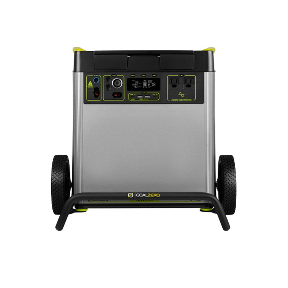
How does a Goal Zero Yeti 6000x inverter not need a ground?
 www.goalzero.com
My goal is to be able to use this as a portable battery and plug it into a reliance transfer switch to power my homes essentials off grid. Or if needed wheel it to my well pump and plug it into my well pump. Or take it camping and plug it into my toy hauler.
I am learning a lot and appreciate your input! Thank you in advance ?
Electric Regards,
?? Firebear
I built this Portable HandTruck battery & inverter. 48volt EG4 Lifepower4 battery & the new EG4 3,000watt inverter. I later found out that the inverter has a Bonded Neutral/Ground that is causing me to have voltage on the entire handtruck frame and battery casing. About 22volts from the Positive terminal to the frame and battery casing and the same from the Negative terminal to the handtruck frame or battery casing. The only conductive connection from the inverter to the hand truck is the frame of the inverter and the 3 bolts that tighten it down to the unistrut. It has worked very well for a few days before I discovered that I had voltage across the entire frame.
Is there a way to properly ground this battery and inverter and keep it portable?
Can I remove the bonded neutral/ground in this inverter and properly have a separate neutral and a separate ground?
Do I need to get a different inverter?
How would you safely make this work and keep it portable???
I got the idea from my design here:
How does a Goal Zero Yeti 6000x inverter not need a ground?
Yeti 6000X
Equipped with 6,071 Watt Hours and seven versatile ports for power-hungry devices and appliances, the Yeti 6000X can power essential home circuits, RVs, trailers, work sites, and more. features YETI 6000X HIGHLIGHTS Goodbye Gas Generator. Hello Yeti X. With a lithium-ion battery at its core, the...
www.goalzero.com
My goal is to be able to use this as a portable battery and plug it into a reliance transfer switch to power my homes essentials off grid. Or if needed wheel it to my well pump and plug it into my well pump. Or take it camping and plug it into my toy hauler.
I am learning a lot and appreciate your input! Thank you in advance ?
Electric Regards,
?? Firebear