diy solar

diy solar

ETC 277AH Grade B?

4 were at home, on the ground near my gate...

1 more to go.

Very quick inspection, battery looks a little cheap with the quick nasty wrapping. They are well packaged though.

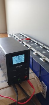
2 sets of bus bars (32 in total) and a quick test showed 3.2v but I only tested 1.

no QR code???
 
The QR code is probably under the top cover. they just haven't cut the hole to show it.

Xuba wrapping is very poor for my cells as well
 
The QR code is probably under the top cover. they just haven't cut the hole to show it.

Xuba wrapping is very poor for my cells as well
Two of my 8 cells from Xuba appear to have original top covers that are more textured and thermo-formed up over the square case protrusions beneath the terminals. They also have cutouts with clear windows over the QRs.
The other 6 look just like yours with smooth black plastic on top, cut clear of the case protrusions and no QRs visible.
 
Crimped some terminals onto the BMS leads, cells are STILL charging in CC mode, hasn't switched to CV mode yet but we're just below that point it seems for a 3.6v setting.

M4 studs/nuts/washers turned up and look to fit nicely so I wont be using the screws.

See if I make any progress this weekend, I have a shed project on the go and everyone has been sick/injured here so no rush lol
 
Will go in to cabinet tomorrow. Hopefully will be using them too. Need to install and play with BMS software too.

I took them to 3.65v, let them rest for a few hours to 3.6v, set it at 3.62 to test current draw and watched it run down from .3 to 0a so I'm comfortable that they are full/balanced.

Took stock of the last few bits needed which I'll grab in town this arvo.
 

Attachments

  • 20210227_144240.jpg
    20210227_144240.jpg
    61.1 KB · Views: 11
OK so the pack is in and working but the BMS doesn't want to play.

It wants a charger connected to the pack after it's all wired in and I don't have a 60v charger - Full pack voltage 57.6.

I've quadruple checked the wiring is as so and tried bridging between the pack main neg and the -p terminal so the inverter could see the battery also, which it could, but the BMS doesn't like it still.

I've contacted JK about it. Currently I have the pack connected directly to take some charge out of it because no doubt this will take a week or 3 and I don't want them sitting there full.

1614489719419.png
 
Now have the pack running "through" the inverter - bridged pack main neg to -p so the inverter could see the battery and push some charge in, which worked, I then removed that bridge and the whole thing is still running/charging etc so it's going via the BMS now but I cannot see it in the software.
 
Did a shutdown test and inverter cannot see the battery after shutdown so I'd have to bridge it again but the manual says

"5.2 After confirming that the above operations are correct, you can power on the protection board. The protection board does not have a power-on control switch, and is designed to be in a charging activation mode. That is, after the battery is assembled, a charger needs to be connected to start the protection board."
 
I just have a boost converter that gives me that voltage to turn it on. I made one myself, but you could use something like this:
https://www.alibaba.com/product-detail/Digital-DC-DC-Boost-Converter-400W_1995771749.html or similar.


I'm picking up a 60v charger from a friend tomorrow :)

So am I correct in assuming it wants to see higher voltage than the pack reference voltage on the load side?

What sort of voltage differential was needed to fire it up?
 
Last edited:
If I remember correctly (and this is not a given) it's a 5V difference. Normally something around 57/58 should be plenty.
I apply the voltage through the BMS, that is, P- to Bat+.
 
I just have a boost converter that gives me that voltage to turn it on. I made one myself, but you could use something like this:
https://www.alibaba.com/product-detail/Digital-DC-DC-Boost-Converter-400W_1995771749.html or similar.
Also, if you could show me how you wire the buck boost convertor I might just get one and leave it setup for if it pack shuts down.

If I remember correctly (and this is not a given) it's a 5V difference. Normally something around 57/58 should be plenty.
I apply the voltage through the BMS, that is, P- to Bat+.

This is my issue then, when I bridged it earlier (pack main neg- to -p) the pack was already at 57.3v and the inverter was set to 57.6 bulk/float so not enough difference.

I've drawn some power out now so it's at 53 or so now.

Do you mean main batt- to p-? i'd have thought going from main batt pos+ to -p side would be a full short/sparks etc
 
You need to consider the BMS part of your battery. Assume you only have two wires coming out: the main battery positive and the P-. All the rest stops existing for now. That's where you apply the voltage, same as where the charger is located.

I have a three step switch in my system:
- step one powers on the boost converter and turns on the BMS
- step two charges the inverter caps through a resistor
- step three powers on the inverter

The boost converter is only momentarily connected to turn on the BMS and then disconnected again.

i'd have thought going from main batt pos+ to -p side would be a full short/sparks

If there is a 60V supply, just like a charger, there is no short.
 
Yes, that's also how the BMS can disconnect the battery from the charger in case there is a problem with a cell.
In terms of polarity.

Charger positive to main batt positive, charger neg to -p or other way round?

With the buck boost convertor, given it has input + and - and output + and -

How are you writing that?
 
- Charger positive to main battery positive
- Charger negative to p-

- Boost converter input + to + of some kind of power supply (a separate battery or something)
- Boost converter input - to + of some kind of power supply (a separate battery or something)

- Boost converter + output to main battery positive
- Boost converter - output to p-

You probably want to add a fuse in there somewhere as well, e.g. after main battery + and treat that as part of the battery as well.
Awesome thanks, I'll grab a boost converter to go with. My 30v power supply for future start ups.
 
Back
Top