diy solar

diy solar

Finally found a LiFePO4 BMS with Low-temp Charging Protection

Yup.... there is a good chance this is a de-featured board. Most of the unpopulated components are near connector 1, 2 & 3 so it is a long shot that any of them work.
That makes sense. Damn! I shouldn't have bought it then, I don't think ... that's the problem with buying a little bit at a time without first specing it all out. I wonder if I'll ever use it now. This hobby is getting interesting. Hopefully I can start using the batteries someday. Currently I'm toying with the idea of either using most of my 20 LiFePO4 batteries in series with a 48V solar inverter, or some other type of setup with sets of 4 LiFePO4's in series (4S for a nominal 12V system) either in parallel or series to the inverter. I'm leaning toward 48V. Huh, I wonder if I could do a bunch of dumb 4S BMS's and then another CanBUS smart BMS that treats those BMS's like 12V cells (thus getting 100% balancing across everything without need for per-cell fusing or anything like that)? Anything is possible, still, including me getting some more LiFePO4's of the same kind and making it a 60V or 72V or whatever if it makes sense, all depending on what solar inverter + BMS combo is best. For simplicity, I think I'll try to get a high-cell-count CANBUS capable BMS and just have one string and an inverter matched to that.

Just to confirm: as long as each string of cells has no parallel cells in it (such as a 4S1P or even a 20S1P) and has a BMS, if I then take another equivilent bunch of cells and BMS (another 4S1P or another 20S1P) and then put both those BMS's in parallel with each other, then I'm good on not needing any cell level fusing, right (the BMSs will individually drop out as each string crosses out of spec)? I think I might take that route if I go with a lower voltage (12V or 24V) system (or even if I do two parallel strings of 48V).
 
Ok, so maybe getting off-topic here since I'm looking at other BMSs, but I noticed that there's another bus called SMBus and I2C. What is that? Also, what about I2C bus? Does that work with inverters? I started another thread for this question:

 
Sorry yes that's my guess, I edited my original post.
Is that a guess or do you have some info on it?

RS 485 uses A & B for signal names so that is a better guess than mine. (I don't know why I didn't think of that, I have used RS-485 many times)
 
Modbus has it's roots in industrial controlls. As an example, I have used it as a communication between a variable frequency drive and a control processor. It is typically used over RS485 or RS486 It is very versatile, but it does not define everything you need to know. Each device has 'registers' that you read to or write to using ModBus and you must know the unique register addresing and format for each device you are going to talk to. (Think of Modbus as a phone. You can call someone with it, but if you don't know their language, you can't communicate)

Note: In the industrial controll space there is also a specification for using the ModBus protocol over Ethernet.

CANBus (Controller Area Network) has it's roots in the Auto industry. (I have even heard it called "Car Area Network") I do not have direct experience with it, but I imagine that without some higher level definition of how to talk to the specific device, you won't be able to control the device. (Just like Modbus)

This lead to an important caution: Just because two devices say they use CANBus or ModBus does not mean they can talk to each other. In fact, unless they specifically say they can talk to each other, they probably can not.

I have not studied CAN bus closely, but from the little I know, ModBus/485 appears superior from a speed and distance point of view. Having said that, CAN bus seems to be the 'hot' thing for device communication. From a sheer momentum point of view, CAN bus seems to be winning.

I have only seen SMBus and I2C in association with PCs and Motherboards.... but that does not mean there are not broader uses.
 
The communication protocol is listed in the download section of the manufacuturer, it dosent look complicated. I has sent a email to "James" for connection port information and never heard back. My BMS has all the connector populated and I received a few extra wires.
 
The communication protocol is listed in the download section of the manufacuturer, it dosent look complicated. I has sent a email to "James" for connection port information and never heard back. My BMS has all the connector populated and I received a few extra wires.
Where did you buy it?
 
From Aliexpress, for some reason the direct link is not working but it's the first item here. I also came with 3 wires on each side.

Model: 4SLFP120A UARTRS485
 
Last edited:
The communication protocol is listed in the download section of the manufacuturer, it dosent look complicated. I has sent a email to "James" for connection port information and never heard back. My BMS has all the connector populated and I received a few extra wires.
Could you please provide a link to where you purchased and the 'Download section' you mention? - Thanks
 
is there a difference between the Lithium Polymer and Lifepo4 models besides the pre-populated settings? It appears that I ordered the former.

Based on the screenshots it seems like you can swap settings...?

H833144193e824da28fafeeeeb943192cJ.jpg
 
we were also talking about max current load. For the 120a unit, the data sheet is quite specific at 130a for 1 second; doesn't appear to be adjustable.
 
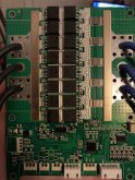
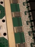
Photos of the boards. No markings on the mosfets but some on the other components.

Any ideas, does this look up to snuff?

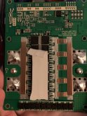
How would electricity flow through the center cable? I’m thinking of unsoldering them and using terminals and bolts.887C5A7E-77C1-42DA-8712-D9C11BBA4775.jpeg482187C6-BB30-4A64-A1E5-F52934975A6A.jpeg4B949835-23F2-413D-BD40-42655E51E4C2.jpeg
 
Each side of the cables is a solid pad under the green mask, so the center cables is connected. you can check the conductivity with a multimeter :)
 
No markings on the mosfets but some on the other components.

That's a bummer. There's no markings or they have been erased?

Any ideas, does this look up to snuff?

Looks like it, well designed (although the layout of the control side is no great, still ok though) and constructed. Not world first class of course but very good for the price ;)

Also, it looks like a true disconnect (mosfets back to back) so it should stop discharging and charging, not just discharging, that's very good.

How would electricity flow through the center cable?

That's not because there's solder mask over the track that the track isn't there, but it's true that at first glance we can think that because the pad for this wire is very different than the other two. Looks like an afterthought, something like "Oh, looks like 2 wires isn't enough... meh, just toss a third pad between the other ones to solder a third wire and call it a day"
 
Last edited:
@boboxx - Sorry for the confusion.. My order shipped yesterday and the screenshot I posted was from their website..I'm hoping that I can simply change to the Lifepo4 settings when I receive my BMS'. Unfortunately I noticed it too late; if someone here could confirm that would be greatly appreciated.


@bostonbuzz Thank you for posting pictures of the board. It appears to be fairly-well designed and those 7-pin mosfets can likely handle 15-20a+ all day, so I'm comfortable with the 120a rating; 130a surge. The data sheet claims the +10a over-current as non-adjustable.


The 10ga wiring and R002 shunt resistors are likely the limiting factors to load/longevity. I wonder what those are?

maybe something like this: https://www.mouser.ca/datasheet/2/54/css2h-5930-935117.pdf
 
Last edited:
Looks like an afterthought, something like "Oh, looks like 2 wires isn't enough... meh, just toss a third pad between the other ones to solder a third wire and call it a day"
I have seen pics of this board on line where the outer two 'holes' have what looks like metal brackets you can screw a lug onto. I suspect when you have that, you don't need the 3rd hole. Consequently, I suspect the design was probably thought through for flexibility of product offerings. Two spots for binding post -or- three spots for wires.

1581440643707.png
 
Back
Top