diy solar

diy solar

Finally got LV6048 Hooked to AC...Now overload?

TheCoachStone

New Member
Joined
Feb 12, 2021
Messages
127
Location
Birmingham, AL
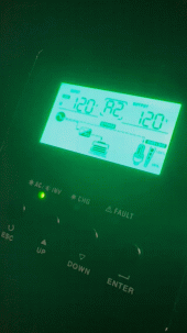
Finally got my LV6048 hooked up to my grid for AC input. I pre-charged the capacitors, turned on the batteries, and turned on the circuit. It turned on and read 120v for input and output. While I was checking all the settings, it started to beep constantly and displayed F07 A2 F00.

The manual says this is an overload fault, but I do not know what could be overloaded. It wasn't even doing anything.
 
got my LV6048 hooked up to my grid for AC input. I pre-charged the capacitors, turned on the batteries, and turned on the circuit. It turned on and read 120v for input and output
Just checking - LV 6048 (Not LVX6048) correct?
Next: you say 120 in and 120 out,
But the MPP LV6048 makes 120 and 240 (Both) with one inverter, or at least it "can" - See page 7 of the manual (digital copy attached)
If you really mean 120 and not 120/240 then you can set it this way.
The Input from Grid must match with the setting for the inverter otherwise you will get that error code.
The LV 6048 has four input terminals G N L1 L2 If you are running on 120 only you may need to jumper L1 and L2.
Check over your set up carefully,
 

Attachments

  • LV6048 split phase manual-20201120.pdf
    3.8 MB · Views: 8
Just checking - LV 6048 (Not LVX6048) correct?
Next: you say 120 in and 120 out,
But the MPP LV6048 makes 120 and 240 (Both) with one inverter, or at least it "can" - See page 7 of the manual (digital copy attached)
If you really mean 120 and not 120/240 then you can set it this way.
The Input from Grid must match with the setting for the inverter otherwise you will get that error code.
The LV 6048 has four input terminals G N L1 L2 If you are running on 120 only you may need to jumper L1 and L2.
Check over your set up carefully,
It is hooked up as a 240 - the LCD reads 120 in and 120 out.

My 28 setting is 2A2.
 
Yes in Setting 28 you should be 2A2
For your input AC you will need 120 and 240 (four wires) and the amperage for AC input needs to be set in Setting 11 - "max utiltiy charging current" the default setting is 30A
 
Last edited:
I hooked up one last week. Everything worked fine until I did a load test doing it with an instant high-current 120v load. Didn't come out so well. It only runs 3kw on each leg. I did a slow run-up on the current draw and it handled it.
 
Didn't come out so well. It only runs 3kw on each leg. I did a slow run-up on the current draw and it handled it.
Yes, internally these units are twin 3kW inverters set side by side in a single box.
I found that using just one, on a single 100Ah battery limited it's output, It was much better after I had two 100Ah batteries connected (and it actually states this in the manual)
Also, if you unbalance the loads 3kW one side and nothing on the other it will go into a fault condition. Adding Anything to the un-used side makes this much better, even just some lights.
I can say with Twin MPP 6048's and a lot more battery behind them, I can run a lot more out of balance without issues.
Together each unit outputs 27.3A 240VAC ie 6.55kW - any larger loads that you can convert to 240 VAC instead of 120VAC cuts the amperage in half, and garantees the load is balanced.
If you are running "Twin MPP 6048's" have you considered going split phase with each unit handling a single leg? Wouldn't that eliminate any balance problems since each unit is running a single leg vs trying to balance both legs on the same unit?
 
The manual indicates parallel connections for each L1 L2 N , and setting up the inverters with one as lead, and one as lag. I can say I have never had any issue with out of balance since parallelling the two inverters, which by that time I also had over 400Ah of installed battery.
You have to remember these units are two inverters in a box, parallel two of them and you actually have four inverters.
The manual doesn't have an option for setting them up single leg, and it would still need comms to keep those two legs properly phase angled.
The 6548 can be set up as you describe, but to my knowlege the 6048 can not. Both produce 13kW output using two units.
 
As a note: I have a large air compressor in the workshop, that is used every day, this is an upright compressor with a 6Hp electric motor to run it. Being an air compressor, it operates in a range 90-135 PSI so the motor from a dead stop, is being asked to not only start spining, but to push against the air pressure in the tank to get the pistion moving. This motor is 240 VAC 1Phase and this means on start up, the loads remain balanced on the inverters.
Another way to address larger motors, is to go with a VFD set up, I have a 1Ph-3Ph VFD that runs a large piece of equipment with a 5Hp 3phase motor, but unlike the air compressor, the VFD set up doesn't have the back-pressure issue.
 
Back to TheCoachStone:
The MPP in your photo is laying on a work bench - so your testing the system I expect.
Not sure, but do you have a battery connected ?
These MPP units will not work unless a 48VDC battery is connected, and has some available current. I know this from my own inital set up, as I got the Inverter before I got the first rack battery. But being me (impatient) I grabbed an E-Bike battery (yes it was 13-S not 16-S) and I mucked about using the small battery, got a nice big nasty spark when I first connected it, but got the MPP to fire up and I played with running a few small loads. The next day after reconnecting the E-Bike Battery the MPP would not start up, and I thought "oh-no, now you've done it" but it was just the small battery had discharged too low a voltage to start the MPP after playing with it the day before. Charging this small battery on a separate dedicated charger it again started the MPP.
This lead me to know:
1. the MPP will only start if connected to a 48 VDC battery,
2. you need to pre-charge with a pencil or a suitable resister before doing the solid connection of the battery to the MPP to charge up the capacitors.
3. If the connected battery voltage is too low, (42VDC) the MPP will not start up.
Yes, it is hooked to 4 12v Ampere batteries at 48v.
 
Check over the comments I put in post #12,
The MPP needs to be connected to a 48VDC battery before being turned on.
Since you have a battery connection open fault, the MPP is not 'seeing' battery voltage, check the connections.
I would turn the unit to OFF
Since you have four separate batteries, connect these in series first, check with a multi meter that you have 48 volts (or more) across the four batteries.
Then connect the neg only to the MPP connection Neg,
Then use a resister or a pencil sharpened at both ends to touch the end of the Pos battery cable to the Pos terminal on the MPP (to charge up capacitors)
Then after the pencil trick, quickly touch the pos to the MPP pos terminal and bolt it down tight.
Then turn the MPP unit ON.
See what happens, report back.
Ok, so I went back this morning and worked on it.

1. Pre-charge capacitors
2. Turn on battery breaker
3. Wait
4. It kicks on the output
5. I turn on the breaker
6. After about a minute it starts to fault

Is it possible my setting for 11 is too low? I'm pretty sure the breaker is a double 40, so should it be set to 80?
 
First up, the battery fault is now cleared - correct? (no fault 56?)
Secondly the setting in 11 is how much the MPP will draw from the grid supply - your 40A breaker doesn't matter, as long as setting 11 is LESS than the breaker. ie the breaker doesn't push the current, the MPP draws upto the limit set in 11.
At point 5. you say turn on the breaker - I assume you mean the grid supply breaker for AC-input (yes?)
When you say at point 6. after about a minute it starts to fault - which fault is this? do you mean the overload fault? please confirm
 
5. Yes
6. This is its new error (attached)

Everything seemed to be working fine, and then it started to beep. Does it think the batteries are over charged?
 

Attachments

  • IMG_0706.gif
    IMG_0706.gif
    11.6 MB · Views: 8
okay,
So it appears the battery connection is fine now, no more fault 56,
Fault code 07 is an overload on the output of 110% (or more) for longer than one minute per the manual page 30.
Do you have any loads on the output?
we didn't discuss that earlier.
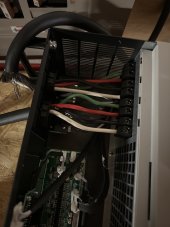
In your photo at post #5 I see output wires attached to the MPP - My suggestion is remove these and try to restart the unit:
A restart means, turn off the MPP, turn off the battery, turn off the incoming Utility power breaker, wait a few minutes; then restart by again using a pencil or resister to jump to the pos to recharge the capacitors, then turn on the battery, turn on the MPP switch, and turn on the utility power.
With no loads, in fact no wires on the AC output there should be no way to have an overload fault.
That said a few settings to double check:
Setting 02 Max charging current - set this to a value at least the same as setting 11 say 30A.
Setting 03 Check this is set to APL (the default setting) this tells the MPP what voltages to expect from the incoming AC utility.
Try the above and report back. - I am assuming you Don't have any PV connected at this stage, if I am wrong, disconnect PV inputs for now while we test.
 
Last edited:
I noticed one more item: the overload occured while the inverter is in by-pass mode.
The inverter should not be in by-pass with little or no loads on it. ie the MPP "thinks" the load is over the capacity of the battery to supply in inverter mode and so it has gone into by-pass to use the utility to run the loads. Check what loads could be occuring. The wires from Posting #5 that are connected to the MPP AC OUT - where do those go? is it possible the wires are in contact (shorted) at the other end? are they connected to a large load like an electrical panel with many circuits ON? For testing purposes we need to remove the output wire for now until we are sure there is no internal short causing the overload condition. Once we confirm that, we can begin to add some small loads and confirm operation.
I will edit the posting above, to say do not apply Utility AC input at this stage, lets narrow the possible causes of the fault.
 
Back
Top