diy solar

diy solar

Finally, the start of my 25kw Ground Mount grid-tie system

If you have more than 2 strings you have to use fuses or you risk damaging the other stings if one string gets a short. So you don't have any choice about fusing unless you can figure out how to combine things to only have 2 strings. Bear in mind that fuses are easily/cheaply available in 600v and 1000v versions, above that I'm not sure what it costs or where you get it. So you'll need to look at the combinations of how much voltage and current you get by combining things different ways. If you have 16 panels per string, that's probably Vmax greater than 600v but less than 1000v, so you'll be able to find fuses, but the box and fuse holders will cost you more money than if you had a lower voltage configuration. I've lost track of how you arrived at the configuration of 16 panels per string, would there be any problem having 12 strings of 8 panels each for example? That would bring your voltages down to a more easily fused configuration. It might even be low enough that you could use breakers, which is much more convenient.
 
I haven't necessarily determined this aspect yet.

Each "String/Series" has a Pmax (Impp) of 10.83A and a Short Circuit Current (Isc) of 11.47A

There are a total of 6 series (16 panels each).

hmm..........

If I grounded each array "Individually" (48 panels) that would be a Short Circuit Current of 34.41A per array (11.47*3) or a combined current for the whole system of 68.82A.

Could I fuse each ground mount array (3 x16 panels)? So there would be two fuses (one for each 3x16) or would I have to separate out the series in each array somehow?

I guess not being familiar with this aspect at all, so any and all input is definitely welcome.

If you do use fuses, they should at least 1.56x Isc of the string they are fusing (and no larger than maximum fuse indicated on panel label.)
If fusing an array with "n" strings in parallel, that fuse should be n x Isc. (but more than two strings in parallel need fuse per string.)
That's also the required wire ampacity.

So either way, seems to me ground wire needs to be 1.56x Isc of the array. Hopefully it would never carry more than one string's current? If separate strings, not connected in parallel. If the strings are paralleled, all would feed into a short. If system has GFCI, I suppose that would (usually) interrupt the circuit and stop current flowing in ground.

It may be that some conduits are allowed to serve as grounding conductor. But those might require bonding across each coupling.
 
Last edited:
@Hedges None of the strings will be in parallel. I don't see any data regarding fuse size on the datasheet. Each string would be fused on the + DC side, is that correct?

Each full array (48 panels) would have ISC of 34.41A x 1.56 = 53.7A. I don't see a way around that since all 48 panels are grounded together on the frame. Then I would need a wire large enough for each array (2 total) to each have a capacity of up to 53.7A, correct?

I don't think fusing would help reduce this at the array. Please feel free to let me know where I'm off on this.

edit: Looking at an NEC table, I would need to have 2x that capacity as well since there would be 10-20 conductors in the same conduit. That would put the wire rating all the way up to 107.4A per array (2 array). So.... I would have to run two 2 gauge copper. Am I looking at this correctly?
 
Last edited:
PV panel and label should list a maximum fuse. That's how much current can be backfed without creating a fire hazard, like overheating the wire. For many panels it is 15A, but probably 20A in your case with 11.57A Isc

If no panels in parallel, likely no fuse required.
Typically positive lead is fused. For some applications like transformerless grid-tie inverters, instructions for mine say to fuse both positive and negative.
It is convenient to have a way to isolate PV strings, like touch-safe fuse holders or breakers. A 2-pole breaker interrupting positive and negative is handy to know everything is disconnected before touching wires.
 
Last edited:
@Hedges I see a max reverse current of 20A, perhaps that may it.

I may add a 2-pole breaker for each array.

I didn't the "earth" ground would be such a large deal. Guess that's what I get for assuming.
 
Here is are a couple "layout" diagrams from the power company. I don't even see mention of a ground on the array.
 

Attachments

  • Inland_Net_Meter_Example_Diagram.pdf
    48.8 KB · Views: 14
  • Inland_Net_Meter_Example_Layout.pdf
    65.9 KB · Views: 13
At least in the US, grounding happens at customer side of meter, and has little effect on utility system.
Permit office looks for NEC compliance, which is where grounding is addressed.
 
I'm reading this: https://www.solar4rschools.org/sites/all/files/PV Grounding REQ's.pdf

It does not copy and paste well here, so I just put the link. Stating that for grounding you can refer to wire size in this table:
https://conduit.site/tables/table-250.122.php It suggests I could get away with 10 gauge if the grounding wire is ok to be with more than 3 wires in a "raceway". It it is subjected to the wire count then I would have to double my current rating for it and that would put me at 107.4A. According to that table, I would have to go with 6awg wire. Surely better than 2, assuming that is correct.


This section stands out:
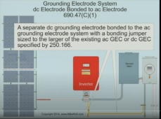
For systems physically separate from the building, such as a pole or ground mounted array, a separate ground rod (bonded to existing grounding electrode conductor) is also required. The use of an additional ground rod is also recommended for installations where chances of lightning strike are high.
 
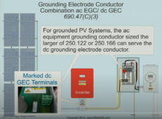
A ground wire can be in conduit with many others, and doesn't count as one of the "current carrying conductors".
But I think its ampacity ought to be derated based on how many current-carrying conductors are in the conduit.

Yes, you can (or are supposed to) have an extra ground rod. But still need the conductor.
 
Listening to this video about the NEC code, it mostly sounds like the ground will take place between the inverter(s) and the Ground Electrode Conductor for the premises (building). He is saying by bonding a ground electrode at the PV to the ground electrode for the building is actually more dangerous due to voltage difference in the event of lighting and that voltage/current then flowing from electrode to electrode.
 
The more ground rods you sink under your array, the more protection you will have from a lightening strike. Sink at least one, two is better, three is fantastic.. Space them 5 or 10 feet apart, bond them all together, run that bond back to the main panel in the house after it attaches to the inverters.

Technically, you can get away with a single ground clamp on each array, but two or three is better.. and from the ground clamp on the array, to the ground rods UNDER the array, you want the biggest wire you can squeeze in there. 6ga minimum, 4ga is better..

Earth grounding is all about resistance.. the lower the resistance, the more effective the grounding is.

You should also figure out what kind of soil you have.. dry soils are not as good as wet soils and you have to go deeper... if your soil is really bad, you may even have to salt it.

We believe our array was struck this summer by a lightening storm.. My wife and I saw the flash, both of us were looking 90 degrees away so it was in our side vision.. She thinks it struck the metal shed behind the array but I think it hit the top corner of the array.. No damage, not even a scorch mark for evidence.. but it did scare the crap out of us.
 
The PV conductors and PV panels have about 600V or 1000V rated insulation, breakdown several thousand volts.
Below that, PV frame could be driven with voltage but not send current through PV wires. Above, they would carry the current.

Ground wire from PV frame back to SCC and ground at house would carry current. Maybe better routed outside house, not going through the equipment? Current flow in ground wire would induce current in PV wires (same polarity in positive and negative wires), so surge arrestors to ground at SCC could help.

He may say it is bad to bond PV and house ground rods together, but I think it is required by code. Without that, short to PV frame could make it high voltage relative to the earth you're standing on while touching it. There would be voltage drop from frame back to ground at house, depending on how resistance was distributed through dirt.
 
Well... this might be in the cards then:

If I can follow this charge for current sizing: https://conduit.site/tables/table-250.122.php

Then 4AWG would allow up to 300A, if I'm interpreting that properly, which is 34.41x1.56x2x2. This is 34.41 x 2 arrays x 2 for being in conduit with 10-20 wires.

I'll talk with my friend who is an electrician as well. If I can get away with running that one wire then that's not tooooooo bad. Just another cost.
 
Solid 4 awg?
Hope you don't have to pull it around any bends.
Even pulling it in a straight line will be a pain, because it comes bent in a roll.

I get 34.41 x 1.56 x 2 x 2 = 215A

34.41 x 1.56 = 54A, would be 8 awg per PV conductor.
4 arrays x 2 wires = 8 current-carrying wires in conduit. NEC says derate 70%
54A / 0.7 = 77A, need wire with that ampacity at 30 degrees C, well NEC says 6 awg 90 degree C rated 75A

edit: Looking at an NEC table, I would need to have 2x that capacity as well since there would be 10-20 conductors in the same conduit. That would put the wire rating all the way up to 107.4A per array (2 array). So.... I would have to run two 2 gauge copper. Am I looking at this correctly?

Where did 10-20 come from? I came up with 8 current-carrying conductors.

What is Voc of your PV strings?
I used 600Voc, more in series less in parallel.
 
I appreciate the assistance everyone! This is the current version of the one line drawing.
 

Attachments

  • one_line_diagram_2021_10_27.pdf
    300.6 KB · Views: 18
There are a total of 96 panels. They are split into 6 series (why do people call them strings?). None of them will be combined. The fronius has a max voltage of 800v, so this is the number that I've worked around and also confirmed my manual calculations on from the fronius calculator. There will be 3 x fronius 15kw units with two inputs on each. Each fronius will receive two strings on their own MPPT.

This puts 6 series of 16 panels each. A DC+ and DC- for each series makes up 12 x 10gauge 2kv wire. I could get away with a little smaller wire, but I figured for the small cost difference that I would go a little larger due to the lower voltage drop and more flexibility down the road if I ever change anything.

Voc is 49.8v
 

Attachments

  • Data Sheet Hyundai Energy Solutions YI HiA-SXXXYI Q3.pdf
    833.8 KB · Views: 5
Back
Top