diy solar

diy solar

First RV upgrade 30A 5th wheel

The general rule for fuses is:

Fuses protect the wire- not the equipment. So size for wire size.

Anytime a you go to a smaller wire - you protect it with a fuse.

So going from a 4/0 wire to any smaller wire needs a fuse.

So yes fuse them at the Lynx bus bar,
 
I've never understood how identical sized cables with same copper can be rated at different amperages based on the jacket material
Ampacity: It’s ALL about the thermal breakdown of insulation, not the melting of the conductors.
Unfortunately most ampacity tables only list the common residential/commercial wiring types THHN, etc. If you want the figures for welding cable, or silicone, you’ll have to go elsewhere and yes the numbers are WAY different.
 
The general rule for fuses is:

Fuses protect the wire- not the equipment. So size for wire size.

Anytime a you go to a smaller wire - you protect it with a fuse.

So going from a 4/0 wire to any smaller wire needs a fuse.

So yes fuse them at the Lynx bus bar,
I'm looking for a diagram review and suggestions based on my interpretation of information gathered. One item I missed is the existing battery cables and disconnect in the rv. I assume leave wiring and disconnect as-is but increase wire gauge of existing battery cable and connect them to the lynx busbar with fuse, not sure of gauge and fuse size?
 

Attachments

  • schematic.png
    schematic.png
    160.7 KB · Views: 6
What wire size is the OEM wire size going into and out of the wiring disconnect switch?

Just fuse for that size of wire.
 
I’ve done a few RV solar/inverter/LFP systems and overall you have most bases covered. Your existing RV battery disconnect switch will stay in place and should cover all DC loads except the inverter.
The length of most of your wire runs aren’t labeled but being an RV gives enough clues as to their lengths. One run that has been trouble for me in the past with LFPs is from the MPPT to the battery. A couple hundred millivolts of IR drop in that run can prematurely trigger the MPPT to switch to float mode, leaving the LFPs at a slightly lower SOC than desired. A check of the run length under full charge current would be suggested.
With your panels in series the breaker rating is pretty high. I would drop it down from 63A to 16A. Or if you think you’ll switch the parallel, go with 32A maybe. Personally I’d use 16.
For equalized battery charge/discharge currents in both batteries connect the positive and negative wires to opposite batteries, not the same battery. Again with LFPs millivolts matter.
Just wonder why you chose a separate charger instead of using your converter and flipping its breaker when on inverter. Convenience?
Is your high current battery to inverter disconnect up to the task? There’s been some threads on this forum about failures there.

Looks pretty good overall.

Good luck
 
The length of most of your wire runs aren’t labeled but being an RV gives enough clues as to their lengths.
Without physical components yet, the AC charger, inverter, SCC and DC/DC should be within 8' of the batteries. I may do cardboard cutouts to get a better idea.
One run that has been trouble for me in the past with LFPs is from the MPPT to the battery. A couple hundred millivolts of IR drop in that run can prematurely trigger the MPPT to switch to float mode, leaving the LFPs at a slightly lower SOC than desired. A check of the run length under full charge current would be suggested.
I would probably run the largest wire that would fit in the SCC or manufacturers specification, but will check it with current meter which I don't have yet.
With your panels in series the breaker rating is pretty high. I would drop it down from 63A to 16A. Or if you think you’ll switch the parallel, go with 32A maybe. Personally I’d use 16.
I will change to 16, I followed a similar diagram and have been tweaking it. Question though: I just read something about using 24V panels for higher voltage, but can't figure out why if the SCC cuts it back to 13.8 or something?
For equalized battery charge/discharge currents in both batteries connect the positive and negative wires to opposite batteries, not the same battery. Again with LFPs millivolts matter.
I thought I did this correct in my diagram.
Just wonder why you chose a separate charger instead of using your converter and flipping its breaker when on inverter. Convenience?
Is your high current battery to inverter disconnect up to the task? There’s been some threads on this forum about failures there.
If I replaced the rv converter with LFP model their charge profile is a constant 14.6V and I prefer the correct profile. The disconnect is a Blue Sea 300A, but I thought about that when I recently changed the 4/0 from 2/0 I had originally put in there. I get mixed information on cable amperage but most people use 2/0 in a system this size.
Thank you for your input, I appreciate the help.
 
Question though: I just read something about using 24V panels for higher voltage, but can't figure out why if the SCC cuts it back to 13.8 or something?
Assuming you have a MPPT charge controller to general thinking is to connect panels in series up to the rated open circuit voltage of the controller. This reduces the amount of copper from the panels to controller.
If you’re using a PWM then you’ll have to run parallel.
 
I get mixed information on cable amperage but most people use 2/0 in a system this size.
Assuming the round trip distance in 2/0 is say 10’ or less you’ll likely be okay. At 20’ round trip I’d do some careful calcs, and compare the full load IR drop to determine acceptability of 2/0.
 
Assuming you have a MPPT charge controller to general thinking is to connect panels in series up to the rated open circuit voltage of the controller. This reduces the amount of copper from the panels to controller.
If you’re using a PWM then you’ll have to run parallel.
Would the reason be to use 24v instead of 12v panels to get more voltage with fewer panels? I guess I'm confused with the 12v/24v difference.
 
Would the reason be to use 24v instead of 12v panels to get more voltage with fewer panels? I guess I'm confused with the 12v/24v difference.
It is a little confusing. There’s really no such thing as a 12v panel. What are referred to as 12 volt panels are actually panels that have an open circuit voltage, Voc, of 19-24 volts depending on how the multiple solar cells are connected inside the panel itself and the temperature.
As a group these are called 12 volt panels because they are often used as part of a 12 volt system (which is also not 12 volts).
The connection from the panel to the battery being charged will likely be through one of two types of charge controllers - PWM (Pulse Width Modulated) or MPPT (Maximum Power Point Tracking). You can Google those terms and get more information. The voltage available from the panel has to be higher than the battery voltage is order to charge the batteries.
 
Being you are installing on an RV, solar watts are EXTREMELY precious!

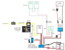
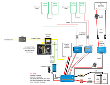
Make sure you go with a high quality mppt solar charge controller (SCC) - since your drawing shows a Victron Smartshunt and would HIGHLY recommend using a Victron Smart mppt charge controller. Having both the Victron Smartshunt (or BMV712) and the Victron mppt SCC, lets you setup a Bluetooth network between the two. The shunt will pass voltage, current, and temperature (if you install an optional temp sensor), the mppt then uses that data to adjust the charging to compensate for wiring voltage losses, useage of power, and if the battery is too cold - doesn’t charge until the battery is warmer.

With the SCC being a mppt, it doesn’t matter if the panels are “12v”, “24v, “36v”, or close to “50v”, it will convert the extra voltage to amps to charge the battery.

For RV’s because we often park in areas that have changing shade, we use more parallel setups than the houses which use more series setups. In one array I have 4 200w panels, I have them setup as 2s2p, two panels in the front area in series, two in the back in series, then those connected into parallel and going into the Victron 100/50 mppt. (Those panels were the “12v” panels- the voltage is about 20v - so I have about 40v going into the mppt - works great!).

For panels, a good rule of thumb (if it is convenient) is to have about double the battery voltage going into the mppt, then go parallel for more panels. But if that is not convenient don’t worry about it. That just keeps voltage high so the mppt starts early in the morning, and then has more in parallel to compensate for the changing shade issues. So if you were to buy 24v or 36v panels, I would connect them in parallel.

Installing panels is a Tetris game, trying to get the most WATTS, into the small space with vents,skylights, air conditioners, etc.

Good Luck
 
I'm starting to shop for components and will probably end up with a Victron SCC, but the solar will be after changing over to lithium and the other components associated with that. I'm using the Lynx power in and adding hardware for fuses, but have not found a quality 40A Mega fuse for the battery charger. According to my diagram, does it seem accurate for this system with possibly increasing to 400W at some point? I'm especially hung up on the 4/0 as opposed to 2/0.
 

Attachments

  • schematic.png
    schematic.png
    160.7 KB · Views: 1
It is a little confusing. There’s really no such thing as a 12v panel. What are referred to as 12 volt panels are actually panels that have an open circuit voltage, Voc, of 19-24 volts depending on how the multiple solar cells are connected inside the panel itself and the temperature.
As a group these are called 12 volt panels because they are often used as part of a 12 volt system (which is also not 12 volts).
The connection from the panel to the battery being charged will likely be through one of two types of charge controllers - PWM (Pulse Width Modulated) or MPPT (Maximum Power Point Tracking). You can Google those terms and get more information. The voltage available from the panel has to be higher than the battery voltage is order to charge the batteries.
I guess my thought process, (being new to this) is looking at Rich solar 200W 12V panel is 24.3 VOC and 200W 24V is 45.4 VOC with both the same physical size-isn't it better to get more power taking up the same amount of space or more power using fewer panels?
 
I've never understood how identical sized cables with same copper can be rated at different amperages based on the jacket material

Heat dissipation and intended application and environment, is what I've been told. But it is perplexing when you look at welding cable vs. battery cable for a marine application.
PVC jacket on most wiring has a low melting and combustion point. And designed to be in conduit or bundled in romex, the aggregate heating from loads in close proximty, the maximum heat tolerance gets assigned for calculations of derating loads.

Single conductors with high temp insulation like silicone rubber can take a lot more heat before losing their protection status.

Also, in free air single conductors dont gain heat from adjacent conductors, plus they more rapidly radiate heat away.
 
I guess my thought process, (being new to this) is looking at Rich solar 200W 12V panel is 24.3 VOC and 200W 24V is 45.4 VOC with both the same physical size-isn't it better to get more power taking up the same amount of space or more power using fewer panels?

Both give the same power 200watts.

If going into a 100/30 (for 2 panels) or a 100/50 (for four panels) with the 12v ones put two in series then go parallel- if you get the 24v ones - put them in parallel. If you put three or more in parallel they need fuses (there are easy MC4 fuses for that). With the 24v and a 100/50 you could go 3p or 4p - whatever fits. With the 12v ones 2s2p (so four panel's). With the 24v do not go 3s - too high of Voc.
 
What wire size is the OEM wire size going into and out of the wiring disconnect switch?

Just fuse for that size of wire.
I have not looked at the OEM wire yet, but since that will also go to the Lynx I'm out of room, so do I really need a fuse for the charger? I also have not found a 40A mega fuse for the charger. I also saw a diagram with a breaker on each side of the SCC, so if I did that then a fuse spot would open up in the Lynx.
 
Changing course a little, I want to start with 2-100w solar panels to deploy on the ground before I put solar on the rv roof, which means I will eventually have two Scc. This is a problem since I'm already full in the Lynx, so looking for options like breakers/fuses in the line and no fuse in the lynx or add busbars off the lynx. Still not sure if the charger needs a spot with a fuse.
 

Attachments

  • schematic.png
    schematic.png
    160.7 KB · Views: 3
The fuse is to protect the wire - not the equipment.

Everything coming off the Lynx needs a fuse - because it (the charger) is going from 4/0 wire to #6 wire. If something weird happens to the charger or the #6 wires rub and get shorted, you want the fuse at the transition to pop when the #6 wire is fully loaded - you don’t want the #6 wire to get overloaded from the battery. (That is why you fuse - it is not for incoming amps / it is for outgoing amps.

You could in one spot on the Lynx, have a 60a fuse - and have #6 wires going to both the 120v charger and the Dc-Dc charger. And do the same thing for both solar charge controllers. As long as the Dc-Dc charger plus the 120v charger don’t exceed 60amps (of input) if both are on at the same time - you are fine.
I find it difficult to size for the wire because every chart I look at is different but I think I have it right?

Not sure this is correct-but except for the inverter everything is an input to the Lynx from the different chargers. Don't like doubling-up but I could put the AC charger on the end of the bus with a mrbf fuse.
 

Attachments

  • schematic.png
    schematic.png
    202.1 KB · Views: 2
I forgot to update the lynx fuse list, and run in to the same problem finding 40A mega fuses for the 2-SCC in the lynx.
 

Attachments

  • schematic.png
    schematic.png
    203.1 KB · Views: 1
Back
Top