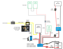
I have a diagram started for this project that needs tweaking-I'm sure. While trying to size the wire and fuses I find cable charts that rate 4/0 90'C @ 260A and others @ 440A. I am new to lithium and solar so my information has come from several sources and now my brain is mush, so any advice is appreciated.


You are using an out of date browser. It may not display this or other websites correctly.
You should upgrade or use an alternative browser.
You should upgrade or use an alternative browser.
First RV upgrade 30A 5th wheel
- Thread starter Scycle
- Start date

scrubjaysnest
Solar Enthusiast
I don't see a 12 volt feed back to the 12 volt side of the distribution panel.
For the charger ac input 14 awg is ok, use the breaker in the distribution panel ac side that fed the old converter. 10 awg from charger to batteries is the minimum but experience, my self and others, 8 or 6 awg would be better.
Different amp ratings on wire result from wire type, temperature ratings, and free air vs bundled or in conduit.
I didn't include the 12v from panel to battery because I plan on using the existing line that will now feed the 12v side of the panel from the battery. The charger needs to come from the transfer switch only live when on shore power to avoid the inverter trying to charge the battery-at least that is what I was told but it makes sense. There will be a 15A fuse in the transfer for the charger, but also need on in the Lynx-maybe 15A also? The range on the cable charts is wide but both were for 90C temp battery or welding cable which could determine if I need to change the 2/0 to 4/0.I don't see a 12 volt feed back to the 12 volt side of the distribution panel.
For the charger ac input 14 awg is ok, use the breaker in the distribution panel ac side that fed the old converter. 10 awg from charger to batteries is the minimum but experience, my self and others, 8 or 6 awg would be better.
Different amp ratings on wire result from wire type, temperature ratings, and free air vs bundled or in conduit.
justinm001
Solar Addict
- Joined
- Dec 18, 2022
- Messages
- 1,535
I've never understood how identical sized cables with same copper can be rated at different amperages based on the jacket material
Heat dissipation and intended application and environment, is what I've been told. But it is perplexing when you look at welding cable vs. battery cable for a marine application.I've never understood how identical sized cables with same copper can be rated at different amperages based on the jacket material
scrubjaysnest
Solar Enthusiast
I'm going with 2/0 from WindayNation, $41 and change for 3 feet of red and black with 3/8 tinned lugs. It's $ 44 and change from Harbor Freight. Seems to up from there.
Edit on ours I leave the charger breaker turned off 99% of the time and solar is always on.
Edit on ours I leave the charger breaker turned off 99% of the time and solar is always on.
The WindyNation 2/0 is rated for 325A which should cover my load if I calculated correctly. Does the cable and fuse size look correct for the 183A inverter load and up to 25A DC load at times? Not sure what size fuse to put in the Lynx for the charger and what happens to the power after the batteries coming from the charger? Will it feed to the SCC or the DC/DC charger?
scrubjaysnest
Solar Enthusiast
Based on cable rating alone, the fuse size would be 325 x 1.25 = 406.25 so a 400 amp fuse. But the Bluesea switch contacts are rated at 300 amps. I'm going with a 300 amp MRBF fuse. Class T might be preferable but I have zero experience with them. I'm also not a fan of cartridge style fuses in mobile applications.
May have been luck I suppose but MRBF have worked fine for me since 2012.
May have been luck I suppose but MRBF have worked fine for me since 2012.
scrubjaysnest
Solar Enthusiast
Scc and charger are parallel sources and I've seen no conflicts there with leaving both on. In my case it is scc and vehicle alternator. 50 amp breaker for the scc and 100 amp between alternator and batteries. Batteries are AGM in my case.
I'm thinking about posting my RV build here as a thread. In the meantime I have a link in a post to my off grid nest thread. It includes all the trial and error discussions with photos. It's, the link, all on the NAZ forum. Thinking and equipment has changed since then. Lessons learned I guess.
I'm thinking about posting my RV build here as a thread. In the meantime I have a link in a post to my off grid nest thread. It includes all the trial and error discussions with photos. It's, the link, all on the NAZ forum. Thinking and equipment has changed since then. Lessons learned I guess.
Hi,
I have almost an indentical set up.
How do you plan to connect the charger to the transfer switch? Cut off plug and connect directly to charger or wire in a female plug to the transfer switch and plug the charger? What brand charger
Also if yiu disconnect the charger/converter, won't you lose the 12V items in your rig?
This is only what I have in mind-I'm no expert. If I can get to the wires in the charger, I prefer to run one single wire, otherwise I would put an outlet near the charger. Victron charger.Hi,
I have almost an indentical set up.
How do you plan to connect the charger to the transfer switch? Cut off plug and connect directly to charger or wire in a female plug to the transfer switch and plug the charger? What brand charger
Also if yiu disconnect the charger/converter, won't you lose the 12V items in your rig?
There is already wire from the DC side of the panel to the batteries used to charge them when AC is connected and power the 12V when no AC is present.
Using my 183+25x1.25=260 so I should have a 300A fuse instead of 250 but the 2/0 would still be large enough cable-correct? Anything close to the 325 should go to 4/0 cable-correct?Based on cable rating alone, the fuse size would be 325 x 1.25 = 406.25 so a 400 amp fuse. But the Bluesea switch contacts are rated at 300 amps. I'm going with a 300 amp MRBF fuse. Class T might be preferable but I have zero experience with them. I'm also not a fan of cartridge style fuses in mobile applications.
May have been luck I suppose but MRBF have worked fine for me since 2012.
I'll have to look in to MRBF, have not heard of that.
scrubjaysnest
Solar Enthusiast
The total wire length from the batteries to the inverter may be a bigger concern and may force larger wire size.
I disconnected my OEM converter. Or rather it is on a separate breaker that I leave off.
Solar keeps the battery up even if I am plugged in to run the air conditioner. Converter can be switched on if difficult conditions persist.
Solar keeps the battery up even if I am plugged in to run the air conditioner. Converter can be switched on if difficult conditions persist.
I would say under 10', less if I can-haven't laid it out yet. The Windynation chart doesn't have distance, it drives me nuts there is no common consistent go-to chart to use. I want to use the correct cable and fuses but it's not cut and dry, although at 260A including safety factor with 300A fuse and 2/0 cable should be sufficient. Is there anything I might add that would require an increase in cable size and I'm assuming it would be only any additional load, such as larger inverter? Would more solar or battery bank require larger cable?The total wire length from the batteries to the inverter may be a bigger concern and may force larger wire size.
scrubjaysnest
Solar Enthusiast
Under the following conditions you should be ok. 2000 Watt inverter at max load= 200 amps. This is allowing 80% efficiency.
Resistance per foot for 2/0 awg @ 77 degrees, 0.0795 from the chart I used.
For 10 feet loss in volts= ixr or 200 x (0.0795x20) = 0.318 Volts
Where we get in trouble sometimes is the volt drop across each connection.
Battery posts, each crimp, fuse connections, switch connections and contacts within the switch. The switch contacts we have no real control over.
I think you see were this can go. Try to keep voltage loss to the inverter at max load under a volt.
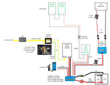
I have no problem going to 4/0 for that short distance, just want it safe and to function correctly. I want to leave room for expansion if I increase solar or battery bank, but I'm assuming that's not a load on the system rather higher current coming in-I think? Starting to look at specific components, new diagram attached.Under the following conditions you should be ok. 2000 Watt inverter at max load= 200 amps. This is allowing 80% efficiency.
Resistance per foot for 2/0 awg @ 77 degrees, 0.0795 from the chart I used.
For 10 feet loss in volts= ixr or 200 x (0.0795x20) = 0.318 Volts
Where we get in trouble sometimes is the volt drop across each connection.
Battery posts, each crimp, fuse connections, switch connections and contacts within the switch. The switch contacts we have no real control over.
I think you see were this can go. Try to keep voltage loss to the inverter at max load under a volt.
Attachments
scrubjaysnest
Solar Enthusiast
For the piece of junk harbor freight I have, 2-2/0 paired 3 foot in length.
For your 30 amp charger 40 amp fuse is good and 8 awg wire unless you really do plan to in large the battery bank. Bigger wire is always better if the budget allows. 4/0 wire to the inverter gives room to grow also and might reduce chances of inverter failure at high loads. I have no data to prove the potential for inverter failure just a gut feeling I get from some 1 star reviews.
For your 30 amp charger 40 amp fuse is good and 8 awg wire unless you really do plan to in large the battery bank. Bigger wire is always better if the budget allows. 4/0 wire to the inverter gives room to grow also and might reduce chances of inverter failure at high loads. I have no data to prove the potential for inverter failure just a gut feeling I get from some 1 star reviews.
Similar threads
- Replies
- 41
- Views
- 1K
- Replies
- 1
- Views
- 260
- Replies
- 15
- Views
- 967