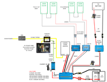
Yes all your wires look sized a size bigger than strictly needed - which is good. It keeps the voltage losses down - especially on the longer runs.
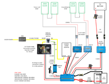
I would have no worries or concerns about combining the two Solar charge controllers into one Lynx spot. Also, because the 120v charger and the Dc-Dc charger won’t be used at the same time- they could also be combined. I would not combine more than two items.
Good Luck
I would have no worries or concerns about combining the two Solar charge controllers into one Lynx spot. Also, because the 120v charger and the Dc-Dc charger won’t be used at the same time- they could also be combined. I would not combine more than two items.
Good Luck