diy solar

diy solar

First system setup! Feedback?

Gabrielle

New Member
Joined
Apr 11, 2022
Messages
76
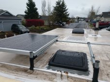
I've just completed the solar setup in my 1987 Toyota mini motorhome. It will primarily run my fridge (freezer converted to fridge- roughly 1/2 kwh per day, I believe), maxair fan and charge my laptop.

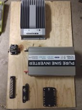
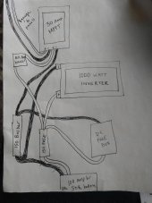
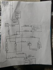
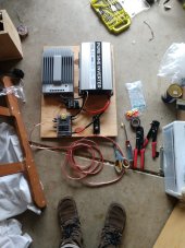
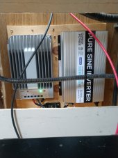
Im starting with 2 100 watt panels and a 100 amp hour lithium sok battery. I went for a 40 amp charge controller so I can size up to 400 watt system in the future. For my needs, I went with a 1000 watt inverter.

Been watching Will's videos and reading his book, studying diligently over the past many moons as I remodeled the RV interior. I was extremely pleased to see the green lights come on yesterday as I finally got everything hooked up and turned on. The fridge humm was a welcome sound.

I'm fairly confident in the work I did, but I'd love some feedback too. If anyone has any comments or ideas about this system please let me know! I can provide more details if need be. Thanks in advance!

(The photos show one panel up on the roof, the set up before mounting and connecting to the battery, and the mounted setup just before connecting panels.)
 

Attachments

  • IMG_20220410_165408139.jpg
    IMG_20220410_165408139.jpg
    301.2 KB · Views: 27
  • IMG_20220411_171232371.jpg
    IMG_20220411_171232371.jpg
    163.9 KB · Views: 28
  • IMG_20220411_181343527.jpg
    IMG_20220411_181343527.jpg
    135.8 KB · Views: 26
The charge controller is connected directly to the inverter and DC distribution?
 
Welcome to the party Gabrielle.

What does your Epever manual say about that connection, if anything? I'm really curious what the inverter manual says about direct connection to a charge controller.
Hey thanks:)

I'll have to do some more reading up. Honestly, the manuals confuse me and I learn better visually so I did read them, but relied more on Wills instruction.
 
I don't know, maybe not..? My brain defaults to an arrangement more like this:

Ahh, I see. That setup does seem a bit more intuitive design-wise. I set up this way based on one of Wills videos for a beginner 400 watt setup. It was different than the book but helped me out to have the dynamic visual. I followed it almost to a T, so hoping this way is okay.. it seems to be working but I want everything to be safe and protected of course.
 

That's the video I based this off of.
I don't have the manuals with me at the moment but everything I'm reading online is saying connecting them directly will destroy my equipment!?

I'm just now seeing the updated version of this setup of Will's. oops
 
As far as I know, most small charge controllers and inverters, like what you are using, will be destroyed through "direct connection".
Yes, Is this a problem?
Yes, I believe this is a problem.
This picture is from the video in post 5. Thanks @corndog for posting.
Gabrielle 001.PNGBy including battery power between the SCC (solar charge controller) and the inverter, you will prevent "Magic Smoke" AKA destroyed equipment. The battery works as a buffer between the SCC and the Inverter.

There is a link in my signature about battery melt down. It is well worth watching to learn the importance of proper materials, assembly techniques and sequence when attaching lugs. Old rides are cool, we don't want to burn yours down or up. (y)

I think Will's video in post 9 is old.
 
Last edited:
As far as I know, most small charge controllers and inverters, like what you are using, will be destroyed through "direct connection".

Yes, I believe this is a problem.
This picture is from the video in post 5. Thanks @corndog for posting.
View attachment 91004By including battery power between the SCC (solar charge controller) and the inverter, you will prevent "Magic Smoke" AKA destroyed equipment. The battery works as a buffer between the SCC and the Inverter.

There is a link in my signature about battery melt down. It is well worth watching to learn the importance of proper materials, assembly techniques and sequence when attaching lugs. Old rides are cool, we don't want to burn yours down or up. (y)

I think Will's video in post 9 is old.
Thanks for the input, definitely don't want anything burning up. I've put a lot of work into this old rig. I unhooked the system and am going to rewire soon and repost!
 
I'm posting as I rework it in hopes that someone has advice on wiring. I felt confident at first with sizing but my brain is having trouble processing it all now. I attached pictures of the new set up, one my hand drawn interpretation of a schematic...

I have 8 gauge running to the panels and 2 gauge wire running from the battery to the busbar and 150 amp mega fuse.

I'm thinking I should do 4 gauge from the inverter to the busbar and fuse, 6 gauge for all the rest of the connections. My logic is coming from what I understand of Wills book, videos, reading on forums, but it's possible that I'm way off here.

OR - I'm thinking 2 gauge also for the inverter to the busbar and fuse and 8 gauge for the rest. These ideas are coming from very different understandings of how the circuits work.

Thoughts??

Thanks in advance for sharing your knowledge, I only want to (re)do this once so trying to get it right!
 

Attachments

  • 0-2.jpeg
    0-2.jpeg
    110.1 KB · Views: 10
  • 0-3.jpeg
    0-3.jpeg
    80.1 KB · Views: 10
Last edited:
I wish I had posted this last week. Maybe this will help or get you started in the right direction as far as wire size.

The thing about wires is, a high quality wire with proper insulation can carry more current than the SAME AWG low quality wire with poor insulation. You should figure out how much current could possibly be carried by the wire, and then select the appropriate quality/size wire.

My first thoughts are:
8awg is too big & not needed from panels to Epever. 10awg should be plenty and easier to work with. 8awg is fine, just overkill.
2awg is common for applications like yours. 2awg should be fine from the battery to busbar, with the fuse. I like the Class-T fuse. When things go bad, I want the problem to be resolved ASAP.
Your inverter is capable of 2000W and the wire to the busbar needs to support that current. If your 4awg can carry that load it will be fine, if not you need to step it up to 2awg or larger.
I do not know the specifications of the wire you are using, so I don't know what the current carrying capacity is.

Here is some more food for thought:
Those resources are so helpful, thanks! That pdf in particular lays everything out in a way that really cleared up some confusion.

I think I'll stick with the 8awg to the Epever, since those wires are already installed from the first time I set this up and I may add panels in the future.

I decided to add a MRBF fuse at the battery, but I'll maybe look into Class-T fuses too.

I ordered 4awg for the battery to busbar and fuse already so I'll go with that. The manual suggests it and also I believe the wire I'm using to be high-quality. Its rated for up to 125C and from that chart it seems it can carry the load.

I've drawn up an updated schematic of sorts. So this is the plan now:
 

Attachments

  • 0-4.jpeg
    0-4.jpeg
    75.3 KB · Views: 3

diy solar

diy solar
Back
Top