diy solar

diy solar

Hello?My 12v setup

A pig with lipstick is still a pig. You spent for all the pretty batteries and such, get/make/use buss bars that can handle the load. For a 4 battery setup there are a few recommended ways to hook up... 5 lugs ...

start at an end and connect all 4 both pos and neg
then the 5th on the negative end A to the shunt.
Then the 5th on the pos end B to the inverter

Now, you want the charge controller (CC) and the inverter on there so I would use a 6 lug bar or 8 if you buy them.
The CC would go on lug 5 and the inverter on lug 6

1706716685886.png

4 batteries, one inverter, some charge controllers?

I would put inverter in the middle, two batteries on each side. Why connect inverter to end and have 100% of current in busbar cross-sections if you can cut it to 50% for free?

I would put charge controller(s) outside that. Why have any busbar voltage drop (due to inverter current) seen by charge controller?
Of course, what is more significant is voltage drop across cable. Some people have wired SCC to inverter, where there is more voltage drop.
 
Ok, I contacted LiTime and asked about the current density the use for figuring their buss bar capacity. Then I did some digging on a few reputable websites. Below is the exchange - I was impressed with the response - it wasn't a brush off.

I am also 100% sure their buss bars are capable of the 300amps listed. Probably a lot more.

Your 16.5x3.5 bars are capable of between 113amps and 228.7 amps --- so not as bad as originally thought but still nowhere near what they are rated at. I would assume they used the cheapest brass they can to make more profit since they already over-rate the bars. That means closer to the 113amps. You could probably use them to gather the CC leads together, then a larger wire to the current shunt on the negative and the classT fuse to the positive.... and stack the lug at the load side of the class T and the shunt with the larger wire used for connecting the invert.

I know you aren't putting them where I listed, but I like how pretty they are.


Expand this quote to see the exchange with litime
Hi,

I did some more digging to verify copper current density and came up with about 4.96 amps per mm^2. Which is on the low end of your figure but still shows 780ish amps.

Without knowing your exact composition of brass 20% lower than copper is a reasonable assumption for good quality brass with a high copper content. Which means 3.96 amps/mm^2.

Poor quality brass with a high tin content would be only 1.96amps/mm^2

Given the quality of all your other products I will assume you are getting best quality brass I get 620amps and poor quality brass would still be 307amps
My apologies for wasting your time I am now very satisfied that the bus bars you produce are capable of carrying the load and I'll post an amazon review to show that. I'll also be keeping them.

Thanks

Robert

References for copper. (just two reputable sources, I found many more)
https://copper.org/applications/electrical/busbar/bus_table3.php
https://ewh.ieee.org/cmte/substations/scd0/wgd3/605 Draft Versions/605-2010.clean.pdf appendix B


On 1/31/2024 2:54 AM, support@litime.com wrote:

Hello Robert,
Hope you doing well.

We have confirmed with our relevant colleagues about it. Our current density coefficient is different from yours.


Our standard is
Purple copper: 5~6 amps/square millimeter
Brass: 4~5 amps/square millimeter

The estimated coefficient is 1.2~1.8 amps/square millimeter according to your current density (according to your current density of about 1000 to 1200 amps/square inch).

Hope for your understanding.

In addition, could you please provide your order number (or order screenshot) for us?

Looking forward to your reply.
Best regards
Patty
 

Attachments

  • just a guess.png
    just a guess.png
    471.1 KB · Views: 2
  • 12v system (2).zip
    3.4 MB · Views: 0
Last edited:
4 batteries, one inverter, some charge controllers?

I would put inverter in the middle, two batteries on each side. Why connect inverter to end and have 100% of current in busbar cross-sections if you can cut it to 50% for free?

I would put charge controller(s) outside that. Why have any busbar voltage drop (due to inverter current) seen by charge controller?
Of course, what is more significant is voltage drop across cable. Some people have wired SCC to inverter, where there is more voltage drop.

I would avoid the cheap-out method and do things nice, neat, safe, and to a standard. You built the system to learn so learn the NEC way verse the 'lets build a van or off-grid cabin' way.
 
Last edited:
Added a few labels ... and attached a few wires so you can move the components and the wires stay attached.
 

Attachments

  • 12v system.zip
    3.4 MB · Views: 2
  • just a guess.png
    just a guess.png
    283.8 KB · Views: 3
Are you going to use a wall charger to plug in ever? i.e. if the sun is covered several days in a row?
 
View attachment 192412

4 batteries, one inverter, some charge controllers?

I would put inverter in the middle, two batteries on each side. Why connect inverter to end and have 100% of current in busbar cross-sections if you can cut it to 50% for free?

I would put charge controller(s) outside that. Why have any busbar voltage drop (due to inverter current) seen by charge controller?
Of course, what is more significant is voltage drop across cable. Some people have wired SCC to inverter, where there is more voltage drop.
I would avoid the cheap-out method and do things nice, neat, safe, and to a standard. You built the system to learn so learn the NEC way verse the 'lets build a van or off-grid cabin' way.

Anything I wrote in that post that didn't follow NEC (besides the dolled-up pig)?

I just suggested order of connections to reduce voltage drop.
 
Anything I wrote in that post that didn't follow NEC (besides the dolled-up pig)?

I just suggested order of connections to reduce voltage drop.
In one post you suggested just stacking all the lugs on a bolt? that is just bad all over. Not interested in a flame war, just seems we think differently.
 
I know stacking multiple terminals is considered not proper. Also putting washers in between (for good reason, resistance if steel. Except for ground terminals.)

I think a stack of ring terminals on a bolt would be a very good connection. Regardless of what code says. Maybe they want it possible to disassemble without a bunch of wires flying loose and shorting.

As for the order of connections to a bus, reducing current through cross section should be an improvement. Although bus should be low enough resistance not to matter. But I would say I could use a 500A bus to handle 1000A total if the current is never over 500A anywhere. Like battery-inverter-inverter-battery.

Having a busbar with extra space is nice for future expansion. The one I bought had a number of holes, but too close and not right size for my terminals. I drilled more, and they are crowded now. I would have been better off making my own, but these have been in place untouched for a few years now.

My new system with two inverters, I'm using a Littlefuse fuse holder that has two set-screw lugs, so handles the inverters, will need to add on if I attach SCC.
 
The problem with stacking is to do with uneven pressure and surfaces and the extra resistance from the different surfaces being in contact and possible different materials. And I would expect it has to do with the wires flying everywhere...

If you put 1 lug per bolt order doesn't matter. After that if you insist on stacking I would do highest current draw closest to the bar. then lesser ones in order... but what if you say have a regular lug then a small ring for a charger, then a regular lug that is on a wire that is larger but really isn't expected to have large current... do you stack them in order by size like the old childs toy with rings? and a washer on top of your pyrimid? How is that going to provide even pressure on all the lugs if they aren't the same size. Same question with a washer.

And most important, it offends my sensibilities :)
 
I like to be senseless, and to offend :)

I've been an IC designer, planning various widths of metallization, placed vias (which thin due to step over edge) scattered out in X and Y to make a layer transition. Without crowding current into some which would cause metal migration.

Clamped connections have a few vanishingly small contact points. Area and resistance depends more on pressure than apparent area.

Stacking could be done badly by someone without understanding, better with knowledge. All the same size, and washer then lock washer then nut could apply force evenly. After that, whole thing is flopping around, so prevent shorts somehow.

Properly rated busbar, suitable terminals, correct torque should reliably meet the need, which is the point of codes. But anything that rotates the terminal could be a problem, e.g. stiff wires. Limber fine strands of battery cable should do much better.

I'm in the process of doing 200A service upgrade, so to those are large wires with small number of large strands. In set-screw lugs, so no ring terminals. But routing the wire, and other wires around them, is a pain.
 
I am kinda sitting back just watching your guys discussion unfold,I know what most people say (2 lugs max on a terminal) but I was always curious as to why, my own brain agrees with hedges and tells me there would be less resistance all joined together as opposed to traveling through a bussbar(more conductor) I see sense in robs example explaining different sized/material lugs how that could cause Hotspots, but let's say there are 4 identical lugs stacked on one nut and bolt, no buss. That would make only 3 contact points that's carrying current. If you take them 4 same lugs and put them on a bussbar instead, stacked 2 lugs on 2 bolts, that would then create 4 contact points that's carrying current through more conductor (buss metal)
 
This is all hypothetical electrical theory though, I obviously do want to learn the NEC way.

P.s. I couldn't open the draw.io file you created for me
 

Attachments

  • Screenshot_20240131_131855_Chrome.jpg
    Screenshot_20240131_131855_Chrome.jpg
    23.3 KB · Views: 2
I am kinda sitting back just watching your guys discussion unfold,I know what most people say (2 lugs max on a terminal) but I was always curious as to why, my own brain agrees with hedges and tells me there would be less resistance all joined together as opposed to traveling through a bussbar(more conductor) I see sense in robs example explaining different sized/material lugs how that could cause Hotspots, but let's say there are 4 identical lugs stacked on one nut and bolt, no buss. That would make only 3 contact points that's carrying current. If you take them 4 same lugs and put them on a bussbar instead, stacked 2 lugs on 2 bolts, that would then create 4 contact points that's carrying current through more conductor (buss metal)

Another point on most bus bars is the length of the bolt used. If it is a bolt sticking up and it is long you can run the nut down on it. If it a short bolt you will run out of space quickly.

The other tidbit on stacking is if you put all the lug on one bolt, say you have 6 lugs - the current from the top one has to travel through the inner ones to reach the bottom.... so you stack with most current. What if you short something and have high up and it has travel through smaller ones... do they melt because they are thin? Does it weld them together?

While looking up stuff for stacking lugs and connections to busbars - it talks about the bus bar rating being 120% of the total number of amps possible from all sources.

In your case to the NEC you have:
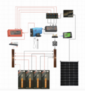
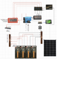
4 batteries capable of 200 amps = 800amps
4 CC capable of 40amps = 160amps
(800 + 160 ) * 120% = 1152amps == so you use your junk yard bars (measure those so we can see the ungodly amount of current they are good for)

The bars are the end of the class T and shunt need to cover 160amp * 120% = 192 amps - use either another set of junk yard bars or buy a set of the LiTime or similar bars.

This covers the event where you drop both inverter cables and they short together and it is sunny. The bus bars don't melt, you get a huge flash, spark/smoke ball and the class T blows and all your cheap breaker melt.


Before you ask, you can't depend of fuses to cut power right away so you need to plan for the full capacity of the batteries before something cuts out.

Post pictures of your cheap breakers and pictures of any labels on them. I'd like to look them up and see if they are melty types.


You can push a lot of amps... this is the issue with 12v ... many times more amps that 24 or 48v
 
Last edited:
Back
Top