diy solar

diy solar

Hello?My 12v setup

I've read on this being a no no. Is a steel washer ok on top of the lug in between the bolt head and lug, but not between the lug and bussbar?

Steel (preferably stainless) on top is fine. Negligible current through bolt.

I have 4 batteries in parallel, none is series. One inverter. I think I understand you by saying halving the current as in put 2 lugs(from batteries) on either end of each bussbar with inverter loads going to the middle of the bussbars?

Yes, that would be an improvement. Maybe not enough if your busbar can't even handle half the current.

What if you just stacked all lugs and ran a bolt through? Battery, battery, inverter battery battery.
Now do that with the bolt threaded into your brass busbar (all lugs on one bolt in one hole). Then you can attach leads from charge controllers, presumably much less current than inverter.

That makes a lot of sense, thanks for clarifying what the issue is with stacking multiple lugs. Before now I never could find a reason not to, I assumed that it would be less resistance because current would be traveling through less conductor. But in you example, I can see how resistance can go up.

I like the piano string look haha, but I will have to do some rearranging to fit my new bus bars and mrbf fuses. Sucks I thought I knew what I was doing and chopped up all my 4/0 wire already.

Well, looks like these buss bars will only handle 2 leads from my charge controllers. Grrrr

General rule of thumb is don't stack lugs, if you must stack no more than 2 on each screw.

Rules were made to be broken, and thumbs get sore when they're in the way.

A fat copper busbar would be nice, though.
Here's mine:


There are two fuses for positive on top. Underneath, busbar with one battery in middle, four inverters attached top/bottom of busbar to either side of battery connection.
 
Ahh ok, this keeps getting more complex haha. I did learn the trick of using a 120v light bulb for the initial connecting, but I suppose your right having measures in place for turning on and off the inverter would be a good protective thing. Do you know how long them capacitors keep a charge?
Not long, not more than a few minutes. If I were designing the circuit with them in it I would place a large high value resistor across them so with power on it wouldn't really affect the circuit and with it off it would drain the voltage so it isn't sitting there waiting to bite someone that touches it. Something like 100 Megaohms, note this isn't any sort of suiggestion it is just an educated guess from working on equipment 30 years ago that had large caps

Note - you can get a disconnect switch that has a OFF/A/B setting... so A has the resistor across it and B has the battery connected... so to turn on you put it in Position A with the resistor inline for a bit until the voltage equalize then B to turn on power before applying any load to the inverter.

You apply inverter load before battery is connected fully and all bets are off... so your startup in that case would be

verify AC breaker out from inverter is off or inverter power is off...
turn to posistion A and wait 30 seconds to a minute
turn to posistion B
turn on inverter or output breaker.
 
Last edited:
Steel (preferably stainless) on top is fine. Negligible current through bolt.


Yes, that would be an improvement. Maybe not enough if your busbar can't even handle half the current.

What if you just stacked all lugs and ran a bolt through? Battery, battery, inverter battery battery.
Now do that with the bolt threaded into your brass busbar (all lugs on one bolt in one hole). Then you can attach leads from charge controllers, presumably much less current than inverter.


Rules were made to be broken, and thumbs get sore when they're in the way.

A fat copper busbar would be nice, though.
Here's mine:


There are two fuses for positive on top. Underneath, busbar with one battery in middle, four inverters attached top/bottom of busbar to either side of battery connection.

A pig with lipstick is still a pig. You spent for all the pretty batteries and such, get/make/use buss bars that can handle the load. For a 4 battery setup there are a few recommended ways to hook up... 5 lugs ...

start at an end and connect all 4 both pos and neg
then the 5th on the negative end A to the shunt.
Then the 5th on the pos end B to the inverter

Now, you want the charge controller (CC) and the inverter on there so I would use a 6 lug bar or 8 if you buy them.
The CC would go on lug 5 and the inverter on lug 6

On the negative you would have a second buss bar that connects to the shunt, the inverter, the CC negative. any other little wires.

I see you have 4 CC so the second buss bar would have 4 for the CC, 1 for shunt wire, 1 for inverter... so you need 6 lugs here ...

Make it pretty and use those spiffy buss bars you picked up... you have plenty

get out drawio and make a spiffy diagram and post it
 
Here, to get you started ... nope, I am not an expert at doing designs.... the zip file is the drawio file (just plain is not an allowed extension)
 

Attachments

  • just a guess.png
    just a guess.png
    507.8 KB · Views: 5
  • 12v system.zip
    3 MB · Views: 3
Nice, I gave up on the draw.io, it kept fighting me. I have another question tho. My charge controller manual says;

Max photovoltaic system input power:
550w/12v
1100w/24v

Am I interpreting this correct that I can only input 1100 watts if my battery bank is 24v?
If so, is there a work around to achieve this kind of input and keep my batteries arranged in 12v? Like possibly a 24-12 v step down converter or buck converter after the scc?
The reason I am asking is because I got rid of my 24v inverter, I only have the 1 3000w 12v inverter in operation, and have a spare 1000w 12v inverter too.
 
What if you just stacked all lugs and ran a bolt through? Battery, battery, inverter battery battery.
Now do that with the bolt threaded into your brass busbar (all lugs on one bolt in one hole). Then you can attach leads from charge controllers, presumably much less current than inverter.
Thanks for thinking outside the box for me, until I get around to rewiring everything, that will be a simple move for now.
A fat copper busbar would be nice, though.
Here's mine:


There are two fuses for positive on top. Underneath, busbar with one battery in middle, four inverters attached top/bottom of busbar to either side of battery coconnection.
Are those all positive leads that I'm seeing? The buss in the center is all your lugs for inverters?
 
Nice, I gave up on the draw.io, it kept fighting me. I have another question tho. My charge controller manual says;

Max photovoltaic system input power:
550w/12v
1100w/24v

Am I interpreting this correct that I can only input 1100 watts if my battery bank is 24v?
If so, is there a work around to achieve this kind of input and keep my batteries arranged in 12v? Like possibly a 24-12 v step down converter or buck converter after the scc?
The reason I am asking is because I got rid of my 24v inverter, I only have the 1 3000w 12v inverter in operation, and have a spare 1000w 12v inverter too.
Must be a 45A SCC, so that is what you have.
No way to charge at 24, but use at 12V.
Youll destroy batteries quickly...
 
What if you just stacked all lugs and ran a bolt through? Battery, battery, inverter battery battery.
Now do that with the bolt threaded into your brass busbar (all lugs on one bolt in one hole). Then you can attach leads from charge controllers, presumably much less current than inverter.

That sounds like a horrible idea to me. Might work until you do something else, but I'd just wait on parts
 
Here's mine:


There are two fuses for positive on top. Underneath, busbar with one battery in middle, four inverters attached top/bottom of busbar to either side of battery connection.

Let's see, the positive and negative looks like a dropped piece of metal and a big short waiting to happen. Stacking like that just rubs me wrong. Drop anything metal on it and best case you melt a tool and blow a bunch of expensive fuses.

Get the waterproof class t fuse holders will help but seems like it ought to have some minimum separation. I'll see if I can look that up in the nec

The lug crimps are hard to see but what I can see isn't pretty. And looks like one is missing heatshrink.
 
Last edited:
Must be a 45A SCC, so that is what you have.
No way to charge at 24, but use at 12V.
Youll destroy batteries quickly...
It's a 40a scc but I see where the math makes 45.8amps..Weird..

Wouldn't a buck converter or similar device convert the volts to amps? Without figuring in losses and loose estimations,

my idea is this... 45amps@24v come out The scc into a 24vto12v converter and outputs 90amps@12v to the batteries. (I know these aren't accurate numbers, just brainstorming)
Also worth noting my batteries are paralelled 4-200ah with 200amp bms's


Second thought is to put my batteries in a 24v configuration and put the buck converter (or different device?) In between the batteries and the inverter
Just get a charge controller for a 12v system, or change everything to 24v. No point in screwing around with weird work arounds.
 
Just get a charge controller for a 12v system, or change everything to 24v. No point in screwing around with weird work arounds.

Agreed, pick a voltage. If you decide to do 2s2p with your batteries make sure to get an active equalizer
 
For me, that would mean buying 4 more identical charge controllers, one for each of my 8-545 watt panels along with more wiring. or another highly expensive 24v inverter. My experience was not good on a 24v system
 
For me, that would mean buying 4 more identical charge controllers, one for each of my 8-545 watt panels along with more wiring. or another highly expensive 24v inverter. My experience was not good on a 24v system
What is the brand and model number of your current charge controller and of your inverter?
 
Let's see, the positive and negative looks like a dropped piece of metal and a big short waiting to happen. Stacking like that just rubs me wrong. Drop anything metal on it and best case you melt a tool and blow a bunch of expensive fuses.

That was the first response I got; post after it says, "it always warms my cockles to see negatives and un-fused positive in such close proximity."

My solution to that will be a sheet of Lucite between negative busbar and positive fuse holders.

In the mean time, disconnect single 4/0 cable with ring terminal to battery terminal. Actually, any jumper in the 8s battery string can be opened to make the busbars safe to work on.

Get the waterproof class t fuse holders will help but seems like it ought to have some minimum separation. I'll see if I can look that up in the nec

These are Blue Sea with snap on plastic covers. I suggest the ones with a latch; these are difficult to remove.


The lug crimps are hard to see but what I can see isn't pretty. And looks like one is missing heatshrink.

You're right about that. Harbor Freight Hydraulic crimper and 2/0 terminals (the 4/0 foreground bottom I bought ready made.)
The "2/0" dies made large wings. They are about right for 4 awg but even then require crimp-rotate-crimp.

The one with red heatshrink was already on end of a cable I cut and used. The red without heatshrink was my attempt.

I plan to buy a quality crimper for up to 4/0 to build cables for another system.
 
That sounds like a horrible idea to me. Might work until you do something else, but I'd just wait on parts

Horrible because people say not to do it?

If you stacked several ring terminals on a bolt, all current going through stacked rings, what in a technical sense is wrong with that? Large cross section from one to the next.

I think it would be as low resistance a connection as possible.
 
Are those all positive leads that I'm seeing? The buss in the center is all your lugs for inverters?

Everything on top layer connected to fuses is positive.
Two 4/0 cables from battery positive fan out to two fuses. Each fuse feeds two 2/0 cables that fan out to two inverters (4 inverters each with internal breaker fed from two fuses fed from one battery.)

Bottom layer is negative busbar.
One 4/0 cable from battery negative goes to middle of busbar.
Four 2/0 cables connect by two bolts to busbar, top and bottom of bar, left and right of battery connection.

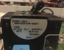
The inverter has 2-pole breaker. Not sure what specs inside these SI 6048US inverters, probably 150A. I just had an SI 5048US open, and the breaker was 125A, 10kA AIC.

The fuses are 350A, which I intend only for catastrophic shorts. The 2/0 cables are protected from overload by breaker at far end.
Single 4/0 is not sufficient for continuous operation of the inverters at full load, but Peukert says I can only get 20 minutes from my 405 Ah 48V bank.

If I had a larger bank (e.g. 1200 Ah 2V cells), those would have dual terminals, or two 4/0 cables between each.

breaker cropped IMG_4546.jpg
 
Back
Top