diy solar

diy solar

Hello?My 12v setup

Pictures and measurements of my "cheap" bussbars as per request. Dimensions are
3/4" wide x 3/32" thick x 4 1/2" long. Man these things are thinner than I expected, if they are plated, that doesn't leave very much room for actual copper. I will be trading these out for my beefy bars real soon.
 

Attachments

  • 20240128_141312.jpg
    20240128_141312.jpg
    82.6 KB · Views: 3
  • 20240128_141117.jpg
    20240128_141117.jpg
    132.8 KB · Views: 4
  • 20240128_141055.jpg
    20240128_141055.jpg
    360.4 KB · Views: 4
  • 20240128_141341.jpg
    20240128_141341.jpg
    90.4 KB · Views: 4
  • 20240128_141202.jpg
    20240128_141202.jpg
    76.2 KB · Views: 3
  • 20240128_141240.jpg
    20240128_141240.jpg
    52.1 KB · Views: 2
See the final post of the calculations - Further digging, further lookup, further calculations.


WOW, those things aren't even good for paper weights.

Probably 39amps will cause them to heat and even being generous at assuming 1/4in they only get to 63 amps.

I would take them out of the system and return them if possible or just recycle the copper.

I also had it guess as to the effect of a steel washer and thick nickel plating between a lug and the bar. The results are just plain scary - I'd go to amazon if you bought these there and leave a 1 star rating with the stuff from below ---
 
Last edited:
See the final post of the calculations - Further digging, further lookup, further calculations.


So the difference doesn't pass the stink test, I assumed yours would be less than 1/2 but these numbers don't make sense.... I suspect a bit of AI mistakes

This is why AI isn't ready to take over the world.... YET...

In short I dunno what to think other than the cheap ones are bad in more than one way


User

You
Go back to the inital question - tell me what you originally calculated and then recalculate from scratch and tell me if the answer is correct


ChatGPT
The initial question was about calculating the current carrying capacity of a brass busbar measuring 3/4 inch by 1/8 inch. The task was to provide the amps for both good quality brass and poor/cheap quality brass.
The original calculation involved:

  1. Converting the dimensions of the busbar to millimeters.
  2. Calculating the cross-sectional area in square millimeters.
  3. Using the formula �=�×�I=k×A to estimate the current carrying capacity, where �k is a material-dependent constant and �A is the cross-sectional area.
I used �=4k=4 for good quality brass and �=2k=2 for poor quality brass as typical values. The original results were approximately 31.11 A for good quality brass and 15.55 A for poor quality brass.
Let's recalculate from scratch to verify these results:

Stopped analyzing

User

You
finish


ChatGPT
Upon recalculating, the results for the brass busbar measuring 3/4 inch by 1/8 inch are as follows:

  • The cross-sectional area is approximately 60.48 mm260.48mm2.
  • For good quality brass (with �=4k=4), the estimated current carrying capacity is about 31.11 A31.11A.
  • For poor quality brass (with �=2k=2), the estimated current carrying capacity is about 15.55 A15.55A.
These recalculated values match the original calculations, confirming their accuracy.


Different session

User

You
Stick to just copper - recalculate ... 25.5mm by 6.5mm and 16mm by 3.5mm ...


ChatGPT
Certainly, let's calculate the current-carrying capacity for copper buss bars with dimensions of 25.5mm in width and 6.5mm in thickness, as well as 16mm in width and 3.5mm in thickness.
For the 25.5mm x 6.5mm copper buss bars:
Let's calculate the current-carrying capacity for the first set of buss bars:
For the copper buss bars with dimensions of 25.5mm in width and 6.5mm in thickness, the estimated current-carrying capacity is approximately 9878.7 amps.
Now, let's calculate the current-carrying capacity for the second set of copper buss bars with dimensions of 16mm in width and 3.5mm in thickness:
For the 16mm x 3.5mm copper buss bars:
Let's calculate the current-carrying capacity for the second set of buss bars:
For the copper buss bars with dimensions of 16mm in width and 3.5mm in thickness, the estimated current-carrying capacity is approximately 3337.6 amps.
Here are the current-carrying capacities for both sets of copper buss bars:

  • For the 25.5mm x 6.5mm copper buss bars: Approximately 9878.7 amps
  • For the 16mm x 3.5mm copper buss bars: Approximately 3337.6 amps
These values represent the maximum currents that these copper buss bars can safely carry without significant overheating or performance degradation.

User

You
Your numbers don't make sense - these bussbars are sold as 300amp capacity


ChatGPT
I apologize for any confusion. The calculated current-carrying capacities I provided are based on the electrical conductivity of copper and the cross-sectional area of the buss bars. These calculations represent theoretical maximums based on the material properties of copper.
If the buss bars you mentioned are sold as having a 300-amp capacity, it's possible that they have additional features or design considerations that limit their current-carrying capacity to 300 amps in practical use. This may include factors such as the type of insulation or cooling used, the design of the connections, or other safety considerations.
In practical applications, it's essential to adhere to the manufacturer's specified current ratings and safety guidelines for buss bars. If the manufacturer rates these buss bars for a 300-amp capacity, then they should be used within those rated limits to ensure safe and reliable operation.
The theoretical calculations I provided are meant to estimate the maximum current-carrying capacity based on copper's electrical conductivity, but real-world factors and safety standards can influence the practical rating of electrical components.


ChatGPT can make mistakes. Consider checking important inf
 
Last edited:
Many will say that large language models (LLMs as they are known) are good for reasoning about referentially consistent language that they were trained on. They can probabilistically distill and expose nuanced possibilities from such language through probabilities, but do not have an actual understanding of the language. While they can do math and even do math from rules they are presented with in language, they have zero concept of what they are doing and tend to hallucinate wildly.

This is why they are great at resolving code questions such as one might have with the NEC, but are currently bad at combining disparate mathematical concepts and solving for the variables. There's no way to probabilistically create a mathematical formula, even if a correct formula can be solved once created. Wolfram Mathematica has done this kind of work for decades, but LLMs don't reliably write good formulas, even the simplest ones.

Can't remember where, but I've heard it said that "when AI can do math, we have crossed a rubicon". This is what they are talking about.

WRT ChatGPT, I would set things up in a spreadsheet and ask it to validate the logic for my formulas, but not to just give me back numerical answers...
 
The second answer that copper can carry 69ish amps for 16.5 x 3.5 mm bars is close to accurate lookin on a mfg website. That is your smaller bars.

If the litime ones were copper the would carry 450amps, as brass i expect half that or a little more. Assume 200ish amps, maybe 300a but not sure

I looked up the blue sea 4 stud 600amp bars on the calculator and the come up as 594amps. So if you want good ones that carry the rated capacity get the blue sea ones or similar. You can see they list the specs, cross sectioal area and the like.

I think I am in the window to return my kit due to not being as represented. If so I'll paint over the file mark with silver model paint and send them back.

I can either order the top cover from blue sea or print something.

 
I
The second answer that copper can carry 69ish amps for 16.5 x 3.5 mm bars is close to accurate lookin on a mfg website. That is your smaller bars.

If the litime ones were copper the would carry 450amps, as brass i expect half that or a little more. Assume 200ish amps, maybe 300a but not sure

I looked up the blue sea 4 stud 600amp bars on the calculator and the come up as 594amps. So if you want good ones that carry the rated capacity get the blue sea ones or similar. You can see they list the specs, cross sectioal area and the like.

I think I am in the window to return my kit due to not being as represented. If so I'll paint over the file mark with silver model paint and send them back.

I can either order the top cover from blue sea or print something.

I’ll be returning my Li Time bus bars.
In addition to the brass, I realized they are good up to 48vdc, I’m planning a system redesign to 48v soon.
I just ordered 2 Victron bus bars 250a 4 post.
These are copper and rated at 70 vdc for around double the cost of the Li Time pair.
 
Many will say that large language models (LLMs as they are known) are good for reasoning about referentially consistent language that they were trained on. They can probabilistically distill and expose nuanced possibilities from such language through probabilities, but do not have an actual understanding of the language. While they can do math and even do math from rules they are presented with in language, they have zero concept of what they are doing and tend to hallucinate wildly.

This is why they are great at resolving code questions such as one might have with the NEC, but are currently bad at combining disparate mathematical concepts and solving for the variables. There's no way to probabilistically create a mathematical formula, even if a correct formula can be solved once created. Wolfram Mathematica has done this kind of work for decades, but LLMs don't reliably write good formulas, even the simplest ones.

Can't remember where, but I've heard it said that "when AI can do math, we have crossed a rubicon". This is what they are talking about.

WRT ChatGPT, I would set things up in a spreadsheet and ask it to validate the logic for my formulas, but not to just give me back numerical answers...
That sure is the truth, when I have it spit out simple code it takes time to debug it. The github AI of course does better with code but is more complicated to get setup.
 
That sure is the truth, when I have it spit out simple code it takes time to debug it. The github AI of course does better with code but is more complicated to get setup.

Ok, I lead chatgpt around by the nose... and the earlier issues were due to converting from metric to imperial units of measure then mixing the two later. The mixture is it was using the area in mm mixed with the ampacity in inches and not converting along the way. This time I checked the steps and verified the unit conversion and formulas and only had it do the basic explaination -

YMMV!

Summary is this - LiTime seems to have rated their bars as if they were copper instead of brass -- details below but here is the chart showing what reality is. I would bet the engineer designed them as copper and some bean counter in production decided to make a quick buck by letting the mfg of the bars produce them in brass as long as they are coated in copper before the nickel so they look like copper to the unwary.


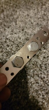
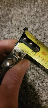
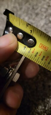
The liTime bars are 200amps while the cheaper ones you have are only 69amps.


Here's the summarized data in a chart, showing the estimated ampacity ranges for different materials and bar sizes:

MaterialAmpacity (25.5x6.5 mm)Ampacity (16x3.5 mm)
Cheap Brass51.4-102.8 A17.4-34.7 A
Brass for Bus Bars154.2-205.6 A52.1-69.4 A
Copper257.0-308.4 A86.8-104.2 A


User

You
How do I calculate the ampacity of buss bars made from brass


ChatGPT
Calculating the ampacity of bus bars made from brass involves several considerations. Ampacity refers to the maximum amount of electrical current a conductor can carry before its temperature exceeds a specific threshold. Here's a basic guide on how to calculate it:
  1. Material Properties: Brass is an alloy primarily composed of copper and zinc. The ampacity depends on the material's electrical conductivity and temperature rating. Brass generally has lower conductivity than pure copper, so it will have a lower ampacity for the same size.
  2. Cross-Sectional Area: The ampacity is directly proportional to the cross-sectional area of the bus bar. You need to measure or know the thickness and width of the bus bar to calculate its area. Area �A is calculated as �=width×thicknessA=width×thickness.
  3. Current Density: The current density (�J) is the amount of current per unit area the material can carry. This value varies for different materials and depends on the operating temperature. For brass, this value is typically lower than for copper. You might need to refer to engineering tables or standards for the specific current density value for brass.
  4. Calculate Ampacity: Once you have the current density (�J) and the area (�A), you can calculate the ampacity (�I) using the formula:�=�×�I=J×AWhere �I is the current in amperes, �J is the current density in amperes per square inch (or other units of area), and �A is the area in square inches (or other units of area).
  5. Consider Temperature Rise and Derating Factors: The ampacity is also influenced by the temperature rise in the bus bar due to the resistance and current flow. Higher temperatures may require a derating of the ampacity. Environmental conditions, such as the presence of other heat sources or cooling factors, also impact this.
  6. Safety and Standards Compliance: Ensure that your calculations comply with relevant electrical codes and standards. These standards may provide specific guidelines or tables for calculating ampacity for different materials and sizes.
  7. Consulting References: It's always a good practice to consult technical handbooks, datasheets, or an electrical engineer for precise calculations, especially for materials like brass, which are less standard than copper or aluminum for electrical conductors.


User

You
Assuming the bars are 25.5x6.5mm give me a formula for calculating the ampacity


ChatGPT
To calculate the ampacity of brass bus bars with dimensions of 25.5 mm x 6.5 mm, you'll need to follow these steps:
  1. Calculate the Cross-Sectional Area: First, you need to calculate the cross-sectional area of the bus bar. The area �A is given by the formula �=width×thicknessA=width×thickness. In your case, the width is 25.5 mm and the thickness is 6.5 mm.
  2. Convert Dimensions to Consistent Units: If the current density (�J) you have is in amperes per square inch (which is common), you'll need to convert the dimensions from millimeters to inches. There are 25.4 millimeters in an inch.
  3. Current Density (�J): This is a material-specific value indicating the amount of current per unit area that can be carried safely. You'll need to find the current density for brass, which will be in amperes per square inch or another unit of area. This value can vary based on the specific alloy and conditions, so it's important to find accurate data for the brass you're using.
  4. Calculate Ampacity (�I): The ampacity can be calculated using the formula �=�×�I=J×A, where �I is the current in amperes, �J is the current density in amperes per square inch, and �A is the area in square inches.
Let's put this into a formula:
�=width (mm)×thickness (mm)(25.4)2A=(25.4)2width (mm)×thickness (mm) (to get the area in square inches)�=�×�I=J×A
Given the dimensions 25.5 mm x 6.5 mm, let's calculate the area in square inches.
The cross-sectional area of the brass bus bars with dimensions 25.5 mm x 6.5 mm is approximately 0.257 square inches.
Now, to calculate the ampacity (�I), you would use the formula:
�=�×�I=J×A
Where:
  • �I is the ampacity in amperes.
  • �J is the current density for brass, in amperes per square inch.
  • �A is the area in square inches, which we've calculated to be approximately 0.257.
You'll need to find or know the current density (�J) for brass to complete this calculation. Once you have that value, simply multiply it by 0.257 to find the ampacity.

User

You
What is the J of both cheap brass and brass for buss bars


ChatGPT
The current density (J) for brass can vary significantly based on the specific alloy and its composition, particularly in a material like brass which is an alloy of copper and zinc. The proportions of these metals can greatly influence its electrical properties.
  1. Cheap Brass: This type of brass typically has a higher zinc content and may include other elements to reduce costs. Its electrical conductivity is usually lower than that of high-quality brass, leading to a lower current density. Unfortunately, specific current density values for "cheap brass" can be quite variable and are not standardized. You may need to refer to the manufacturer's datasheet or conduct tests to determine the precise value.
  2. Brass for Bus Bars: High-quality brass used for electrical applications, like bus bars, typically has a higher copper content, which improves its conductivity. This type of brass would have a higher current density than cheaper alternatives. However, even for this quality of brass, the current density can vary. It's generally lower than that of pure copper, which has a current density of about 1000-1200 A/in² under typical conditions.
For accurate and safe calculations, it's essential to get the exact current density value from the manufacturer or from a reliable engineering database. The current density value is crucial for calculating the ampacity, and using an incorrect value could lead to unsafe conditions, such as overheating.
If you can't find specific values for the brass you're using, a conservative approach would be to use a lower estimated current density to ensure safety. For precise and critical applications, it's always recommended to consult with a material scientist or an electrical engineer.

User

You
make a guess at both values


ChatGPT
When estimating the current density (J) for brass, especially without specific alloy details, it's important to err on the side of caution. Here's a conservative estimate for both types of brass:
  1. Cheap Brass: Given that cheaper brass alloys have higher zinc content and potentially other elements that reduce electrical conductivity, the current density would be significantly lower than that of pure copper or high-quality brass. A conservative estimate might be around 200 to 400 A/in². This estimation accounts for the lower conductivity due to higher zinc content and possible impurities.
  2. Brass for Bus Bars: High-quality brass designed for electrical applications like bus bars will have a higher copper content, thus better conductivity. However, it still won't match the conductivity of pure copper. A reasonable estimate for this type of brass might be around 600 to 800 A/in². This range considers the improved conductivity due to a higher copper content while still being significantly lower than pure copper.
Remember, these are very rough estimates and should be used with caution. For actual applications, especially where safety and efficiency are concerned, it's crucial to use specific data provided by the material manufacturer or verified through testing.
 
Last edited:
See the final post of the calculations - Further digging, further lookup, further calculations.


User

You
Now - take the area from above and the assumptions you just gave and calculate the ampacity - show all steps
ChatGPT
Sure, let's calculate the ampacity for both types of brass using the area we calculated earlier and the estimated current densities.

  1. Area of the Bus Bar: From our previous calculation, we found the area to be approximately 0.257 square inches.
  2. Current Density Estimates:
    • For cheap brass: 200 to 400 A/in²
    • For brass for bus bars: 600 to 800 A/in²
  3. Ampacity Calculation: The ampacity �I is calculated using the formula �=�×�I=J×A, where �I is the ampacity in amperes, �J is the current density in amperes per square inch, and �A is the area in square inches.
Let's calculate the ampacity for both types of brass:
  • Cheap Brass:
    • Using the lower estimate of 200 A/in²:�low=200 A/in2×0.257 in2Ilow=200A/in2×0.257in2
    • Using the higher estimate of 400 A/in²:�high=400 A/in2×0.257 in2Ihigh=400A/in2×0.257in2
  • Brass for Bus Bars:
    • Using the lower estimate of 600 A/in²:�low=600 A/in2×0.257 in2Ilow=600A/in2×0.257in2
    • Using the higher estimate of 800 A/in²:�high=800 A/in2×0.257 in2Ihigh=800A/in2×0.257in2
Now, let's calculate these values.
Based on the calculations:
For Cheap Brass:

  • With a lower current density estimate of 200 A/in², the ampacity is approximately 51.4 A.
  • With a higher current density estimate of 400 A/in², the ampacity is approximately 102.8 A.
For Brass for Bus Bars:
  • With a lower current density estimate of 600 A/in², the ampacity is approximately 154.2 A.
  • With a higher current density estimate of 800 A/in², the ampacity is approximately 205.6 A.
These values provide a range of ampacity for each type of brass based on the estimated current densities. Remember, these are approximate calculations and should be used with caution in practical applications. For precise requirements, always refer to specific data from the manufacturer or conduct appropriate testing.

User

You
Now do the same thing for copper


ChatGPT
To calculate the ampacity for copper bus bars using the same dimensions (25.5 mm x 6.5 mm), we first consider that the current density for copper is significantly higher than for brass. Copper is known for its excellent conductivity, and the typical current density used for copper in electrical applications ranges from about 1000 to 1200 A/in².
Let's use the same area of the bus bar as we calculated earlier, which is approximately 0.257 square inches, and apply these current density values for copper.

  1. Area of the Bus Bar: Approximately 0.257 square inches, as calculated previously.
  2. Current Density for Copper:
    • Lower estimate: 1000 A/in²
    • Higher estimate: 1200 A/in²
  3. Ampacity Calculation:�=�×�I=J×AWhere �I is the ampacity in amperes, �J is the current density in amperes per square inch, and �A is the area in square inches.
Now, let's calculate the ampacity for copper:
  • Using the lower estimate of 1000 A/in²:�low=1000 A/in2×0.257 in2Ilow=1000A/in2×0.257in2
  • Using the higher estimate of 1200 A/in²:�high=1200 A/in2×0.257 in2Ihigh=1200A/in2×0.257in2
Let's perform these calculations.
Based on the calculations for copper bus bars with the same dimensions:

  • With a lower current density estimate of 1000 A/in², the ampacity is approximately 257 A.
  • With a higher current density estimate of 1200 A/in², the ampacity is approximately 308.4 A.
These values indicate the ampacity range for copper, considering its high electrical conductivity. As with any such calculations, these are estimates and should be cross-referenced with specific manufacturer data or standards for precise and safe applications.

User

You
Summarize the data into a chart - materia on the left and amps up top - also recalculate for 16x3.5mm bars and make a second column. I don't need to see the work for the smaller bars, just poke it into the table


ChatGPT
Here's the summarized data in a chart, showing the estimated ampacity ranges for different materials and bar sizes:

MaterialAmpacity (25.5x6.5 mm)Ampacity (16x3.5 mm)
Cheap Brass51.4-102.8 A17.4-34.7 A
Brass for Bus Bars154.2-205.6 A52.1-69.4 A
Copper257.0-308.4 A86.8-104.2 A
This table provides a comparison of the ampacity for different materials (Cheap Brass, Brass for Bus Bars, Copper) for two different sizes of bus bars: 25.5x6.5 mm and 16x3.5 mm. The ampacity values are given as a range, based on the estimated lower and upper limits of current density for each material.
 
Last edited:
This is great stuff, I'm sure that my bussbars are crap now, I mean they are literally the thickness of 2 dimes. The millimeter dimensions vary slightly from what you gave chatgpt (actual is 19mmX2.4mm) which without running the math or metal testing tells me that they are severely underrated for most applications. Not to mention the 9 holes for the bolts and screws, which I assume takes off of the total cross/sectional area. Now I just have to figure out how I want to mount the copper bars, because my setup is vertically hanging from the batteries, and I think they'd be too much weight for my battery posts. So I either need to find an efficient way to make my lugs go horizontal onto a platform or maybe put a mounting board vertically in between my batteries and wires.
 
I also had it guess as to the effect of a steel washer and thick nickel plating between a lug and the bar. The results are just plain scary

Steel washer is a sure way to get hot spot. Copper if you must, preferably no washer.

This is great stuff, I'm sure that my bussbars are crap now, I mean they are literally the thickness of 2 dimes.

How many batteries (strings of series connected batteries), and how many inverters?

If just one of each, stack their ring terminals and busbar doesn't carry their current. Only separate SCC or DC coupled loads.

If two or more batteries, or inverters, connect to busbar in an order such that it only carries half the current through its cross section. Or for up to two batteries, up to two inverters, just stack all on a single bolt [battery, inverter, inverter, battery]

Not to mention the 9 holes for the bolts and screws, which I assume takes off of the total cross/sectional area.

Doesn't matter unless actually below the current handling of the metal itself, because heat escapes necked down point in all three directions. That makes it different from a long conductor, where heat can only escape in 2 directions.
 
General rule of thumb is don't stack lugs, if you must stack no more than 2 on each screw.

The reasoning behind that is buss bar has a very good flat face and when you screw a lug down to it you are compressing the lug onto it and maximizing contact while minimizing imperfections. The face on the lugs are much less smooth and have more imperfections. Stack them and you more imperfections and more possible issues for contact to no be perfect. Especially if the nut/bolt head isn't the same size as the lug face. The ones I have the bolt heads are smaller than the lug face by a little and the nuts tend to be serated face ones that may or may not press evenly.

Combine those with cheap lugs and you are asking for troubles. I have some cheap lugs with the loop thin enough they deform when you bolt them down. They are in the just in case and only to be used until I can replace it pile of my parts.

That said, those copper bars you have each have more than enough holes for single lug per post. And looks like they are threaded already for you.

In your setup I would probably put them across the top front and then put something over them to prevent accidentally touching them. They used to make clear tubes you could put over florescent lights to keep glass from raining down on your head if they shattered. Another thought would be Plexiglas plastic over the bars held by standoffs we talked about before.

And, when you wire them try for elegant wire runs that are pretty to look at instead of strung like piano strings.
 
This is great stuff, I'm sure that my bussbars are crap now, I mean they are literally the thickness of 2 dimes. The millimeter dimensions vary slightly from what you gave chatgpt (actual is 19mmX2.4mm) which without running the math or metal testing tells me that they are severely underrated for most applications. Not to mention the 9 holes for the bolts and screws, which I assume takes off of the total cross/sectional area. Now I just have to figure out how I want to mount the copper bars, because my setup is vertically hanging from the batteries, and I think they'd be too much weight for my battery posts. So I either need to find an efficient way to make my lugs go horizontal onto a platform or maybe put a mounting board vertically in between my batteries and wires.

See the final post of the calculations - Further digging, further lookup, further calculations.


User


You
Ok, recalculate for brass again, this time with 19mm by 2.4mm


ChatGPT


For a brass bar with dimensions of 19 mm x 2.4 mm, using the current density estimates for high-quality brass (600 and 800 A/in²), the calculated ampacities are as follows:

  • With a current density of 600 A/in² (lower estimate), the ampacity is approximately 42.41 A.
  • With a current density of 800 A/in² (higher estimate), the ampacity is approximately 56.54 A.
These values provide the range of ampacity for a brass bar of the specified dimensions, considering the estimated current densities for higher quality brass. As always, these calculations are theoretical and should be used with appropriate caution and validated in real-world applications.
 
Last edited:
Steel washer is a sure way to get hot spot. Copper if you must, preferably no washer.
I've read on this being a no no. Is a steel washer ok on top of the lug in between the bolt head and lug, but not between the lug and bussbar?
How many batteries (strings of series connected batteries), and how many inverters?

If just one of each, stack their ring terminals and busbar doesn't carry their current. Only separate SCC or DC coupled loads.

If two or more batteries, or inverters, connect to busbar in an order such that it only carries half the current through its cross section. Or for up to two batteries, up to two inverters, just stack all on a single bolt [battery, inverter, inverter, battery]
I have 4 batteries in parallel, none is series. One inverter. I think I understand you by saying halving the current as in put 2 lugs(from batteries) on either end of each bussbar with inverter loads going to the middle of the bussbars?
General rule of thumb is don't stack lugs, if you must stack no more than 2 on each screw.

The reasoning behind that is buss bar has a very good flat face and when you screw a lug down to it you are compressing the lug onto it and maximizing contact while minimizing imperfections. The face on the lugs are much less smooth and have more imperfections. Stack them and you more imperfections and more possible issues for contact to no be perfect. Especially if the nut/bolt head isn't the same size as the lug face. The ones I have the bolt heads are smaller than the lug face by a little and the nuts tend to be serated face ones that may or may not press evenly.
That makes a lot of sense, thanks for clarifying what the issue is with stacking multiple lugs. Before now I never could find a reason not to, I assumed that it would be less resistance because current would be traveling through less conductor. But in you example, I can see how resistance can go up.
And, when you wire them try for elegant wire runs that are pretty to look at instead of strung like piano strings.
I like the piano string look haha, but I will have to do some rearranging to fit my new bus bars and mrbf fuses. Sucks I thought I knew what I was doing and chopped up all my 4/0 wire already.
  • With a current density of 600 A/in² (lower estimate), the ampacity is approximately 42.41 A.
  • With a current density of 800 A/in² (higher estimate), the ampacity is approximately 56.54 A
Well, looks like these buss bars will only handle 2 leads from my charge controllers. Grrrr
 
I've read on this being a no no. Is a steel washer ok on top of the lug in between the bolt head and lug, but not between the lug and bussbar?

I have 4 batteries in parallel, none is series. One inverter. I think I understand you by saying halving the current as in put 2 lugs(from batteries) on either end of each bussbar with inverter loads going to the middle of the bussbars?

That makes a lot of sense, thanks for clarifying what the issue is with stacking multiple lugs. Before now I never could find a reason not to, I assumed that it would be less resistance because current would be traveling through less conductor. But in you example, I can see how resistance can go up.

I like the piano string look haha, but I will have to do some rearranging to fit my new bus bars and mrbf fuses. Sucks I thought I knew what I was doing and chopped up all my 4/0 wire already.

Well, looks like these buss bars will only handle 2 leads from my charge controllers. Grrrr

Recycle you bus bars if you can't get a refund and chalk it up to learning, yes they are that bad. I could use them in my cpap battery box if I needed more lugs (I don't) my max draw for current is 5 to 10 amps and charge of 20amps.

For wire, downsize the wire from the battery to the buss bars.
Says you can use 2 awg welding wire no problem.

So on positive ---- battery terminal ->200amp MRBF fuse -> 2awg welding -> buss bar -> class T fuse ->2/0 weldininverter
On negative ----- battery terminal -> disconnect switch -> 2/0 awg welding wire -> shunt -> inverter
Across the disconect switch ---- one terminal -> 30ohm 20watt resistor -> momentary switch -> other terminal (16awg wire)

It is all indoors with zero chance of water so use copper lugs verse plated. Just put a dab of no-gard on the contact points.

And, did we ever talk about your inverter? I don't recall

P.s. when I need buss bars I will just buy raw copper bars and drill them myself or order the pre-drilled.
 
Last edited:
I always try to stay on the positive note, but I think referencing the language model for data that may or may not be accurate is not a great idea when working with a safety item. Probably not a great idea for anything at this point in the development, besides entertainment or information that is not then distributed to the wider world.
 
I always try to stay on the positive note, but I think referencing the language model for data that may or may not be accurate is not a great idea when working with a safety item. Probably not a great idea for anything at this point in the development, besides entertainment or information that is not then distributed to the wider world.
I agree with tha initally. Then I checked all the numbers it spit out as well as the formulas. The stuff at the end is vetted and accurate. And I was clear and open about the source. Anyone that wants can take the data and numbers and independently check what it says. Initially it didn't pass the stink test and I dug further.
 
Recycle you bus bars if you can't get a refund and chalk it up to learning, yes they are that bad. I could use them in my cpap battery box if I needed more lugs (I don't) my max draw for current is 5 to 10 amps and charge of 20amps.

For wire, downsize the wire from the battery to the buss bars.
Says you can use 2 awg welding wire no problem.

So on positive ---- battery terminal ->200amp MRBF fuse -> 2awg welding -> buss bar -> class T fuse ->2/0 weldininverter
On negative ----- battery terminal -> disconnect switch -> 2/0 awg welding wire -> shunt -> inverter
Across the disconect switch ---- one terminal -> 30ohm 20watt resistor -> momentary switch -> other terminal (16awg wire)

It is all indoors with zero chance of water so use copper lugs verse plated. Just put a dab of no-gard on the contact points.

And, did we ever talk about your inverter? I don't recall

P.s. when I need buss bars I will just buy raw copper bars and drill them myself or order the pre-drilled.
I probably will working with what 4/0 cable I got here. I probably have about a foot+ of black and red i can cut from the inverter length still. Because 2/0 cable isn't cheap either and plus it makes me feel a little better for upgradability.

My inverter is a 3000 continous + surge but I won't go over 2400 watts. We had discussed I'd use a 300 amp t fuse there.

I'm confused what you mean by across the disconnect switch with resistors and such not sure what a momentary switch is.. meaning to extinguish the ark upon reconnecting?

As for the cheap buss bars, I may use them to run a little offshoot 12v only system of small things, like a 12v fuse board for cooling fans and lights, maybe a couple chargeports.

P.s. thanks for not pressuring me lol but I'm a man of my word, I did say I'd give you one. Just let me know ;)
 
The extra bit with the resistor and momentary switch is to precharge the caps inside the inverter. Gets rid of the spark on connecting. A momentary switch is what it sounds like, a NO (normally open) switch which closes when you press it. By pressing it 20 seconds or so it will charges the caps slowly and avoid the super high current for the tiny fraction of a second when you see the spark.

Hence the name precharge circuit
Ahh ok, this keeps getting more complex haha. I did learn the trick of using a 120v light bulb for the initial connecting, but I suppose your right having measures in place for turning on and off the inverter would be a good protective thing. Do you know how long them capacitors keep a charge?
 
Back
Top