diy solar

diy solar

Grid tie system with small critical loads battery backup

This sounds similar to what I described?


The correct way to do this is with a single neutral to each point, from a central connection.
Example:
A wire trough under the 3 pieces of equipment. (Main panel, sub panel, inverter)
A neutral terminal block in the trough. And a single neutral from the terminal block to each piece of equipment.

Yup. Tee connection formed in wiring trough.
(I hadn't read all the words and formed a picture in my mind. When I provide pictures to clarify my writing, it is usually an image stolen from the web.)

An upside of trough vs. conduit Tee like I used is much greater cross section for additional runs. And ability to tap off more conduit sections.

See, I'm learning from you guys on this forum!
I now have a 24" trough under my house where four electrical panels connect, and will put a 36" one between my Sunny Islands and the garage loads panel.
I also used a 3R trough above PV combiner panel at my old place.
 
For code.
Can you give the NEC code reference number for this requirement?

All current carrying conductors of a circuit must travel together.
Then a common neutral point violates this requirement. At the common neutral point, neutral currents will combine but the line1 and line2 wires won't. So the current doesn't travel together any more. The neutral wire from the common point to the main panel is a combination of multiple different circuits now. To say it another way, if you lift the neutral from the main panel to the common neutral bar, you are interrupting multiple circuits.

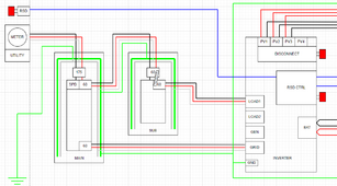
Tell me how to modify my drawing to achieve what you are asking for because I see no possible way to do it.

1715803825798.png

If you lift one of the neutrals, while loaded. There is a possibility of a spark
The voltage differential is millivolts due to the low resistance of the alternate neutral path, thus no spark, no hazard.

And if you become the completion of the circuit, you will be the current carrying conductor.
The other neutral path is vastly less resistance than you will ever be, thus no hazard.

When you break a circuit in the middle. One side should be the source end , and the other should be the load end.
Grid interactive inverters can do both at the same time. They can sink and source power at any given moment so the current can flow in either direction.

Mike C.
 
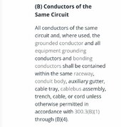
Can you give the NEC code reference number for this requirement?
300.3 (b)Screenshot_20240515_162907_Chrome.jpg


Then a common neutral point violates this requirement. At the common neutral point, neutral currents will combine but the line1 and line2 wires won't. So the current doesn't travel together any more. The neutral wire from the common point to the main panel is a combination of multiple different circuits now. To say it another way, if you lift the neutral from the main panel to the common neutral bar, you are interrupting multiple circuits.
Lifting any neutral only interrupts the circuit (feeder) it's running with.
Tell me how to modify my drawing to achieve what you are asking for because I see no possible way to do it.
Draw it as I described above.
The voltage differential is millivolts due to the low resistance of the alternate neutral path, thus no spark, no hazard.
And if the other neutral has already lost connection (no way of knowing), you are going to be in for a surprise.
The other neutral path is vastly less resistance than you will ever be, thus no hazard.
That's assuming that it's in play.
Grid interactive inverters can do both at the same time. They can sink and source power at any given moment so the current can flow in either direction.
Current still only flows in one direction. (One or the other at any time)
And when the connection is lost, grid-tied inverters are designed (required) to disconnect.
 
Draw it as I described above.
You can't.

You can vaguely say how to do it, but when you actually try, you find out it can't be done like you think it can be done.

Any place you put this common neutral bar necessarily means some circuit is sharing a neutral wire with another circuit.

The only way I can see it would actually work is to put in a 3 pole transfer switch and switch the 2 lines *and* the neutral to the backup panel so that neutral either follows the main panel breaker line or the inverter load line. This of course means the interlock breaker concept can't comply with your interpretation of the code since the power comes from two different places but your aren't switching the neutral to align with that.

Not trying to argumentative here, but I've yet to see any way you can make the neutral behave the way you think it should and use a breaker interlock for transfer to a backup panel.

Mike C.
 
You can't.

You can vaguely say how to do it, but when you actually try, you find out it can't be done like you think it can be done.
I have installed many systems in real life, this way.

Adjust your drawing so that the wiring is ran across the bottom of everything.
Like a ladder diagram (if that's familiar).
The neutral will be drawn from the left most piece of equipment to the right most piece of equipment. And a single tap to the center piece of equipment.
The Line conductors will travel as you would expect. (Without taps)
 
Adjust your drawing so that the wiring is ran across the bottom of everything.
The neutral will be drawn from the left most piece of equipment to the right most piece of equipment. And a single tap to the center piece of equipment.
The Line conductors will travel as you would expect. (Without taps)
Like this?

1715808575100.png

The main to backup, the main to inverter, and the inverter to backup lines all travel in different conduits. When the inverter supplies power to the backup panel, the neutral currents now go along the grid feed, to the main panel, and then to the backup panel. This violates your rule.

I await a more precise wiring explanation of how neutrals should be wired. There are four neutral points to be wired: main panel, backup panel, inverter grid, and inverter load. I see no way to wire them such that neutral ONLY carries the current of its circuit with no loops. A backup panel that can be powered from two sources necessarily introduces a neutral loop if you don't switch the neutral. I don't see a way around that.

Like I said, the only solution that meets your objective is a 3 pole transfer switch which negates a breaker interlock system.

Mike C.
 
That wire you have running between "Main" 60A breaker and "Inverter" Grid terminal?
Just run it through same conduit as "Inverter" Load1 terminal, through Sub-panel, back to main panel. Then down inside main panel to "Main" 60A breaker.

Two red, two black, one white, one green. White and green can land on busbars in each panel.

(or if not in conduit, in a trough as Tim says).
 
Like I said, the only solution that meets your objective is a 3 pole transfer switch which negates a breaker interlock system.
Don't break the neutral, that would turn it into separately derived systems.
Which just adds more complications.
 
Two red, two black, one white, one green. White and green can land on busbars in each panel.
I wasn't aware you could share neutral between two circuits.

When the inverter is running, the grid input and the load output are using the same neutral wire in the conduit. Is that okay?

Mike C.
 
That is something to consider.
As drawn, Sub panel either is powered by main panel, otherwise by inverter. Doesn't seem overloaded.

If Load2 was also connected, then both sub panel and whatever is on load 2 would pull current through it, so size accordingly.

I think you could run a second neutral through same conduit, simply flying by sub panel without connecting.
That would still work when inverter supplies sub panel; path would be back to main, then turn around and come through conduit a second time to reach sub. That's about what I've done.
 
Yes
Input and output are not using it at the same time.
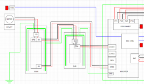
Well, they seem to be. To illustrate, I've drawn what I think you guys said:

1715811103631.png

One conduit goes from man to backup, carries one neutral, one ground, and two sets of hots (backup panel or inverter grid). Technically, both could be used at the same time (backup on grid power only, inverter charging from grid or pushing back PV).

Another conduit goes from backup to inverter, carries one neutral, one ground, and two sets of hots (inverter load, inverter grid). These will generally be in use at the same time for normal operation (backup on inverter load, inverter grid either sucking power during dark or pushing PV back to grid during day).

This doesn't feel right to me, but let me know if it is, or if I failed to capture the directive.

Mike C.
 
Better size the neutral for 120A, between main and sub panel.
I don't know if NEC would have any issues, but that works electrically.

I would draw the panel boxes bigger and route the lines representing wires through them, to make it clear they never separate from N and G.
 
One conduit goes from man to backup, carries one neutral, one ground, and two sets of hots (backup panel or inverter grid). Technically, both could be used at the same time (backup on grid power only, inverter charging from grid or pushing back PV).
Backup on grid and charging, yes.
Not pushing back and charging. (This would be either/ or)
Another conduit goes from backup to inverter, carries one neutral, one ground, and two sets of hots (inverter load, inverter grid). These will generally be in use at the same time for normal operation (backup on inverter load, inverter grid either sucking power during dark or pushing PV back to grid during day).
This is also either /or.
(Referring to neutral currents only)

At any given time, current only flows in one direction on a conductor.
(From the higher voltage side to the lower voltage side)
 
By the way, I would put interlocked backfed breaker in main as well, in case I wanted to supply some of those loads.
It does mean you don't see when grid returns.

I've since implemented Load Side Tap instead - 200A main breaker only or meter main, fan out after that to main loads panel, inverter, backed up loads panel.

My system doesn't have the double current in N issue because my inverter is fed by main panel (with its own N), then feeds output of inverter through same conduit back into main panel, then out to sub-panel.
 
Also, your drawing still shows two neutrals at the center (sub panel) equipment.
I would have a tap there, so that there's a single neutral to each piece of equipment.
 
how do you make the neutral connection in the trough? It's making sense now, but I won't backfeed a breaker in the main panel. I'll make sure I get what I want in the critical loads subpanel and be happy with that. Power is quite stable where I am building, better than what I have now. I have made do with a few extension cords and a Honda 2000, this will be the lap of luxury by comparison. :)
 
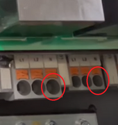
I used split bolt inside a conduit body. Also wrapped it but since it is zero volts I wasn't concerned about pointy ends poking through tape like I would for L1/L2.

I like Polaris. By selecting sufficiently oversize, I'm able to slip insulation through connector (of the type open on both ends) and set-screw onto a 1" section of exposed conductor after removing insulation in the middle. A 2-port connector supports 4 ends that way.

Tim - grounding lug in trough? I'm thinking lay-in lug, connect to middle of ground wire.

Should Skyking use Polaris for Neutral as well? That would support one more end for the lug. Or daisy-chain through ground bar in sub panel? One more wire back to lug?

My new setup has multiple panels I'll interlock and backfeed with #2 from inverter. One gets primary power 2/0 (and ground #4) through a different conduit. I'll stitch the neutral and ground (make some loops) to ensure it always has a path together with L1/L2. The conduit path is already a loop.
 
mciholas said:
Another conduit goes from backup to inverter, carries one neutral, one ground, and two sets of hots (inverter load, inverter grid). These will generally be in use at the same time for normal operation (backup on inverter load, inverter grid either sucking power during dark or pushing PV back to grid during day).

This is also either /or.
(Referring to neutral currents only)
That makes no sense. The inverter decides, moment by moment, if the grid path sinks or sources power. Power *WILL* flow in *BOTH* grid and load lines at the same time. It *HAS* to that's the whole point of a grid interactive inverter. The combined neutral from the inverter will carry both the grid and load neutral currents mixed together. Is that what is intended?

At any given time, current only flows in one direction on a conductor.
Sure, at the nanosecond level, that is always true in every wire. In fact AC is defined as always changing direction.

None of this advise makes any sense to me. I'm advised not to have neutral loops, but you guys are creating one neutral for TWO circuits with this layout. I also can't believe the "put it in a trough" changes anything. How do the electrons know or care what box they are in?

Simple question: is my latest wiring diagram "right"? If not please explain *exactly* how it would change. There are four neutral things to connect: main neutral bar, backup neutral bar, inverter grid neutral, inverter load neutral. Now tell me how they are connected.

Mike C.
 
The combined neutral from the inverter will carry both the grid and load neutral currents mixed together.
It won't
The inverter is either a source or a load, at any given time.
I also can't believe the "put it in a trough" changes anything.
It simplifies the installation. And gives you a place for the tap.
How do the electrons know or care what box they are in?
Echolocation (sonar)
Maybe?
There are four neutral things to connect: main neutral bar, backup neutral bar, inverter grid neutral, inverter load neutral. Now tell me how they are connected.
Actually 3
 
It won't
The inverter is either a source or a load, at any given time.
The single neutral line to the inverter is carrying the neutral currents from the GRID input/output (varies) to the inverter *AND* the LOAD output.

The single neutral between main and backup panels is carrying the neutral currents from both the inverter GRID input/output (varies) *AND* the backup panel if it is in grid mode.

NEC 200.4(A):

Neutral conductors shall not be used for more than one branch circuit, for more than one multiwire branch circuit, or for more than one set of ungrounded feeder conductors unless specifically permitted elsewhere in this Code.

Isn't sharing the neutral between two circuits on the inverter a violation of this clause? It doesn't matter if the wires are all in one conduit or not.

If I did this, does the neutral have to be rated for the combined circuit ratings? 120 amps?

Actually 3
No, my inverter has a neutral connection for the GRID and the LOAD that are separate.

1715863313076.png

Thus I have main panel neutral, backup panel neutral, inverter grid neutral and inverter load neutral. 4 points.

Again, simply tell me how you wire those four points together and not combine neutral current from two circuits and without creating a neutral loop? I can't see anyway to do this.

The simplest would be to send every neutral to the backup panel neutral bar. Main neutral, inverter grid neutral, inverter load neutral all go to the backup panel neutral bar making it the single point neutral. That would be equivalent to a stand alone neutral bus bar where the backup panel to bus bar neutral wire is zero length.

The separate inverter neutrals are basically tied together at both ends, so that's electrically one wire so they will share current and not be segregated. Tis does mean the main to backup neutral is combined with backup panel and inverter grid current.

I am going to be wiring this up in a few days, so I am keen to figure this out.

Mike C.
 

diy solar

diy solar
Back
Top