diy solar

diy solar

Ground/neutral bond? (EG4 3kw)

If I had to pick one, I would say no N-G bonds is worse than multiple N-G bonds.
Hi FilterGuy, thank you so much for all your contributions on this forum and the awesome resources you created on grounding.

Could you please elaborate on the above comment? My understanding is below:

With two N-G bonds, grounded enclosures in the path will be partially energized creating a shock hazard.

With no N-G bond, we have two hots instead of a hot and a neutral as their potential to the ground is unknown. As there is no path through earth to the source, the shock hazard should be low. If we have a ground fault, we will basically create an N-G or Hot-G bond. The latter would inverse the outlets polarity creating a dangerous situation for devices relying on polarized plugs. It would take a second ground fault to close the circuit and trip a breaker.

In short, it appears it takes a ground fault to create a safety hazard without an N-G bond while a safety hazard may always between two N-G bonds.

Let me know what I'm missing!
First.... the best answer is and always will be one and only one NG bond in the system. Anything else is not a good idea.

Now, to my comment.
Without an NG bond, if hot shorts to a metal case or other conductive object that is grounded, The item will be hot but nothing will clear the fault. This means the object will remain a shock hazard indefinitely.

Multiple N-G grounds will not typically creat a shock hazard unless someone is working on the system.
 
Without an NG bond, if hot shorts to a metal case or other conductive object that is grounded, The item will be hot but nothing will clear the fault. This means the object will remain a shock hazard indefinitely.
This is what I thought initially as well but then realized that for a a battery-powered inverter without an N-G bond there is no path to the source through earth so the hot touching a grounded case may not be a shock hazard as the current has no path through a person back to the source. This is very different with utility power as the curbside transformer is grounded so there is always a path back to the source through earth.

Coming back to the case of a battery-powered inverter, it appears to me that a hot-to-ground contact could simply result in setting the black wire as the neutral wire, as the black wire will now be at the reference ground potential, and the white wire as the hot wire correspondingly. In short, a polarity swap on the outlets but the grounded enclosure is not actually energized as it can be with multiple N-G bonds.
Do you disagree with the above?
 
Coming back to the case of a battery-powered inverter, it appears to me that a hot-to-ground contact could simply result in setting the black wire as the neutral wire, as the black wire will now be at the reference ground potential, and the white wire as the hot wire correspondingly. In short, a polarity swap on the outlets but the grounded enclosure is not actually energized as it can be with multiple N-G bonds.
What hapens in pass-through mode? wouldn't that tie hot to ground?
 
From a safety perspective having N-G loops is safer than not having grounds.

The basic issue with relation to current code and best practices is current passing through the ground rather than neutral under load. Ideally all current returns to source via the neutral and not the ground.

My Opinion, not advice:

Go to anyone's house in the US and put a clamp meter on a ground. I bet you 99 times out of 100 there's current going through it because our world is imperfect.

There are two issue IMO with this.

One listed above is creating Antennas that interfere with other devices both in your home and in your larger area.

The other is ground wire sizing. If you have current returning to source via the ground, you need to at minimum be sure the wire is capable of safely handling that load.

Some may point to safety concerns of working on a system because if you detach a ground in a multi-loop system you haven't interrupted the circuit.

I would argue this is a nanny state mentality of trying to make everything overly safe. If you're working on any electric circuit it is your responsibility to understand and test what you're working on before you start taking it apart. For your own safety, not to satisfy some words on paper somewhere.
 
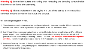
After investigating and working with this class of inverters, I have decided I can longer recommend them for anything other than single inverter installations. I understand that many people will have a different point of view on the issues, and I respect that, but it is not something I would recommend.

I have added the following to my resource on how to wire the MPP LV6548 and EG4 6500EX-48.

1670441165615.png
 
I think the solution for the NEC issue is to change NEC, not stop using new technologies. The problem is the code, not the safety of the inverters.
 
I think the solution for the NEC issue is to change NEC, not stop using new technologies. The problem is the code, not the safety of the inverters.
If I thought the NEC requirements were unnecessary, I would agree. However, the NEC requirements are not superfluous. They are there because of real problems (and deaths) that have been seen in real installations.

The problem is not due to some new technology making the code obsolete. The problem is that the bad design of these inverters do not allow for the proper setup that follows the NEC requirements. Schnider and Solark do not have these problems because they design for a common neutral and do not attempt to do dynamic NG bonding. Victron does dynamic NG bonding because they are designed for mobile installations but they have provisions to disable the bonding when necessary.

The sad thing is that the changes needed to make these inverters more appropriate for stacking are very small. If they just documented and supported removing the bonding screw that the hardware already has, the systems would be usable for stacking.
 
I certainly agree the bonding screw should be accessible. It shouldn't even be a screw if it's not meant to be removed.

I also agree the mobile/non-mobile use cases bring different requirements to the table.

I would argue against the NEC guidelines on loops as they are developed with a grid centric and a one size fits all solutions. My problem with them is in the name of safety they pound every peg into a round hole regardless of the cost and likelihood of incident in specific circumstances.
 
I would argue against the NEC guidelines on loops as they are developed with a grid centric and a one size fits all solutions. My problem with them is in the name of safety they pound every peg into a round hole regardless of the cost and likelihood of incident in specific circumstances.
There are certain places where the NEC gets it wrong, but I am not convinced this is one of them.

The nice thing about this forum is that the reader can see different points of view. This is one of them.
 
What hapens in pass-through mode? wouldn't that tie hot to ground?
Yes the situation is very different in pass-through as we can assume that we always have an N-G bond at the main panel so a ground fault (hot to ground) will trip a breaker. I guess one could speculate that if pass-through mode is regularly used then it can prevent a fault going unchecked even if an N-G bond is missing in battery-powered mode.

In any case, it may obviously be preferable to have a common neutral configuration or the option of dynamic N-G bonding. For inverter/chargers that do not bond N-G internally (as the AIMS LF-series I'm trying to install), one could achieve the correct N-G bonding with a relay at the subpanel triggered by the AC-input to the inverter/charger although it will not be completely in sync with the built in transfer switch so there will be some incorrect transients.
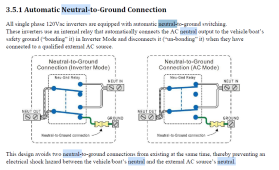
 
For inverter/chargers that do not bond N-G internally (as the AIMS LF-series I'm trying to install), one could achieve the correct N-G bonding with a relay at the subpanel triggered by the AC-input to the inverter/charger although it will not be completely in sync with the built in transfer switch so there will be some incorrect transients.
Interesting. Acording to this manual the Global LF Series does internal dynamic bonding.


1670468850977.png
 
AIMS has a large number of LF inverter variants. The ones with model numbers ending in V, VR, or VS have dynamic N-G bonding, which can be disconnected. The ones with model numbers ending in AL do not have dynamic N-G bonding, with the neutral floating in inverter mode. I had incorrectly assumed that they would be operating in common neutral as a result, with only the hot disconnected by the built in transfer switch. I have asked if they can be operated in common neutral with the input and ouput neutrals connected externally but have not heard back yet.
 
Got the following reply from AIMS technical support: "You can not tie input neutral and output neutral together as they are two separate sources and both current/voltage carrying lines. You will destroy the inverter."

I doubt this is the correct technical answer as the N is kept at constant potential via the N-G bond in the main panel and there is just a short transient when both sources operate at the same time with no opportunity I can see in the circuit diagram for current from one source to pass through the coil of the other source. However, I'm sure it is the easiest and most convenient answer for them to provide. In any case, looks like I'll be setting up power relays for dynamic N-G bonding if I want to keep the warranty.
 
Any updates on this? Looks like EG4 3KW units have been/are shipping with the grounding screw removed (no N-G bond in any mode) like some of its bigger brothers and sisters. Rather than deal with slow customer support and/or opening the darn thing up, I'd prefer to connect the neutrals together. Honestly from pictures/video I've seen where other people "fix" the N-G bond (adding or removing) I'm slightly concerned that there's no way it could survive a 30A short to ground anyways...

tl;dr: Do we have an answer on connecting Neutral In and Out assuming it's a static install connected to and powered by the main panel (with N-G bond) and the unit is feeding a sub panel (without N-G bond)
 
Coming back to the case of a battery-powered inverter, it appears to me that a hot-to-ground contact could simply result in setting the black wire as the neutral wire, as the black wire will now be at the reference ground potential, and the white wire as the hot wire correspondingly. In short, a polarity swap on the outlets but the grounded enclosure is not actually energized as it can be with multiple N-G bonds.

Do you disagree with the above?

I'm no expert, just speculating, not offering advice. But I believe the consequence of what you describe is comparable to using an isolation transformer to prevent shock when working on electronics.

Go to anyone's house in the US and put a clamp meter on a ground. I bet you 99 times out of 100 there's current going through it because our world is imperfect.
To illustrate your point - A couple years ago I was melting lead on a hot plate and got a mild shock. I checked and it was about 50 volts to ground (in the US, 120vac line). I presumed electricity was leaking through the heating coil but not a true/full short. So I replaced the cord with a grounded cord and grounded the frame of hot plate. I assume the hot plate leaks a bit to ground now, but doesn't zap me anymore.
 
Back
Top