


theHouserHouse
New Member
- Joined
- Sep 5, 2020
- Messages
- 27
I want to make sure we get the grounding correct on our travel trailer solar system. We have decided to go a different direction and build a kind of solar generator mounted inside the dinette bench and just plug our RV's shore power cored into it.
I've read the product manuals and here's what they have to say about grounding...
GROUNDING INFO FROM THE MANUALS
Victron SmartSolar MPPT 150/60-Tr Solar Charge Controller:
● Battery grounding: the charger can be installed in a positive or negative grounded system.
Note: apply a single ground connection (preferably close to the battery) to prevent malfunctioning of the system.
● Chassis grounding: A separate earth path for the chassis ground is permitted because it is isolated from the positive and negative terminal. (would this be inverter ground?)
● The USA National Electrical Code (NEC) requires the use of an external ground fault protection device (GFPD). These MPPT chargers do not have internal ground fault protection. The system electrical negative should be bonded through a GFPD to earth ground at one (and only one) location.
● The charger must not be connected with grounded PV arrays. (one ground connection only)
● The plus and minus of the PV array should not be grounded. Ground the frame of the PV panels to reduce the impact of lightning.
VertaMax Inverter:
The VertaMax is designed to work with grounded electrical systems. In the inverter, ground is not connected to the input terminals. .Use a copper wire to connect the grounding terminal on the VertaMax enclosure to earth ground or chassis ground. The grounding terminal is located on the DC Input end of the inverter.
Vehicle installations: Connect to the chassis of the vehicle.
Do not connect the system negative conductor to this terminal. NEC requires to use of an external ground fault protection device (GFPD). The system electrical negative should be bonded through a GFPD to earth ground at one (and only one) location. The grounding point may be located in the solar/wind circuit or the battery circuit.
After reading both of these instructions I think the following is how to ground this system.
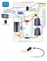
· Ground the batteries. I believe this can be done at the battery monitor shunt, on the side of the shunt closest to the battery. The ground wire will connect to the chassis.
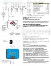
· Ground the frame of the PV panels. We have 8 panels: 2 pairs are mounted together. This sounds like I need to ground the 4 separate panels and the 2 pairs, 6 grounding points all together. Ground them to the chassis.
· Solar Charge Controller grounding not needed because the ground is at the battery shunt.
· Inverter grounding ?unsure? The manual says to ground at the chassis, but the charge controller says only one grounding point. So I’m thinking no additional ground for the inverter, just the one ground at the battery shunt.
In the attached diagrams, the green wire is the ground.
Thoughts?
I've read the product manuals and here's what they have to say about grounding...
GROUNDING INFO FROM THE MANUALS
Victron SmartSolar MPPT 150/60-Tr Solar Charge Controller:
● Battery grounding: the charger can be installed in a positive or negative grounded system.
Note: apply a single ground connection (preferably close to the battery) to prevent malfunctioning of the system.
● Chassis grounding: A separate earth path for the chassis ground is permitted because it is isolated from the positive and negative terminal. (would this be inverter ground?)
● The USA National Electrical Code (NEC) requires the use of an external ground fault protection device (GFPD). These MPPT chargers do not have internal ground fault protection. The system electrical negative should be bonded through a GFPD to earth ground at one (and only one) location.
● The charger must not be connected with grounded PV arrays. (one ground connection only)
● The plus and minus of the PV array should not be grounded. Ground the frame of the PV panels to reduce the impact of lightning.
VertaMax Inverter:
The VertaMax is designed to work with grounded electrical systems. In the inverter, ground is not connected to the input terminals. .Use a copper wire to connect the grounding terminal on the VertaMax enclosure to earth ground or chassis ground. The grounding terminal is located on the DC Input end of the inverter.
Vehicle installations: Connect to the chassis of the vehicle.
Do not connect the system negative conductor to this terminal. NEC requires to use of an external ground fault protection device (GFPD). The system electrical negative should be bonded through a GFPD to earth ground at one (and only one) location. The grounding point may be located in the solar/wind circuit or the battery circuit.
After reading both of these instructions I think the following is how to ground this system.
· Ground the batteries. I believe this can be done at the battery monitor shunt, on the side of the shunt closest to the battery. The ground wire will connect to the chassis.
· Ground the frame of the PV panels. We have 8 panels: 2 pairs are mounted together. This sounds like I need to ground the 4 separate panels and the 2 pairs, 6 grounding points all together. Ground them to the chassis.
· Solar Charge Controller grounding not needed because the ground is at the battery shunt.
· Inverter grounding ?unsure? The manual says to ground at the chassis, but the charge controller says only one grounding point. So I’m thinking no additional ground for the inverter, just the one ground at the battery shunt.
In the attached diagrams, the green wire is the ground.
Thoughts?


")