diy solar

diy solar

Grounding roof mounted system - confused

neo2299

New Member
Joined
Sep 4, 2023
Messages
42
Location
Missouri
I just ordered new inverters and panels to upgrade/change my current system. I'm super confused by the grounding as I'm seeing many conflicting answers. My main questions are:
1. Do I just run a ground wire from the mounts to my main electrical panel grounding?
2. Do I need a separate rod only connected to the roof mounts?

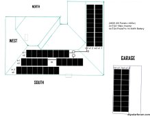
I'll attached a photo of the system design and info. I don't care about code issues... What is the best way overall?
SOLARDRAWING.jpg
 
Last edited:
So if i'm reading this correct you're saying just run copper from the roof mounts to the main panel ground bus bar?
It doesn't have to go directly there.
Usually it's ran along with the PV conductors. In your case, to the 18kpv ground bar. Which is in turn connected to the existing grounding system, along with the AC conductors.
 
It doesn't have to go directly there.
Usually it's ran along with the PV conductors. In your case, to the 18kpv ground bar. Which is in turn connected to the existing grounding system, along with the AC conductors.
Awesome, I appreciate the help... That was basically the conclusion I had figured but alot of conflicting info online
 
If your existing ground rod for the house is outside and readily accessible I would, and have, connected outside solar panels etc. directly there.

I see no reason to bring the ground wire inside the house to connect it to a ground bar with a connection that goes right back outside the house.
 
If your existing ground rod for the house is outside and readily accessible I would, and have, connected outside solar panels etc. directly there.

I see no reason to bring the ground wire inside the house to connect it to a ground bar with a connection that goes right back outside the house.
The object isn't to get to the ground rod.
It's to get to the N/G bond.
How you get there isn't that important. But NEC requires that the EGC be ran along with the PV wires. And it's easier than splitting up the wires, and running them in two different directions.
 
One grounding system, always.
It's not grounded, if kept separate.
Not necessarily true.
My house is like 50 meters away from my solar panels. The inverter is obviously in the house and it grounds at the house grounding.
Since my panels are very far away, instead of running a 50 meter grounding cable to the house ground, I built a new mini grounding grid (copper rods, copper wires) on my land where the panels are located and grounded the frames right there.
So now the house has its original grounding grid and the panels 50 meters away got their own dedicated grounding grid. If they get hit by a lightning for instance, they are grounded right there in the field. Inverter and every other appliance in the house are grounded at the original house grounding grid.
So what do you exactly mean by "not grounded if separate"?
 
I am not an electrician, sometimes around the house when no one is looking I will pretend to be one.
It is my understanding that all your grounding rods need to be bonded together to make one grounding system. When I put a sub-panel in a garage or other structure I bring 4 wires in. Green wire from main panel to sub-panel. Drive new ground rod at sub panel and connect to grounding bar along side with the green wire.
If not bonded it will tend to attract lightning instead of protect from.
I use EMT conduit and run an addition green wire to ensure bonding from ground rod at the panels to the system grounding.
 
If your existing ground rod for the house is outside and readily accessible I would, and have, connected outside solar panels etc. directly there.

I see no reason to bring the ground wire inside the house to connect it to a ground bar with a connection that goes right back outside the house.
You think that way because you don't make a living as an electrician. Tim's way is the ONLY correct way to do it.
 
I am not an electrician, sometimes around the house when no one is looking I will pretend to be one.
It is my understanding that all your grounding rods need to be bonded together to make one grounding system. When I put a sub-panel in a garage or other structure I bring 4 wires in. Green wire from main panel to sub-panel. Drive new ground rod at sub panel and connect to grounding bar along side with the green wire.
If not bonded it will tend to attract lightning instead of protect from.
I use EMT conduit and run an addition green wire to ensure bonding from ground rod at the panels to the system grounding.
Bonded together even when they are quite far away from each other, in my case 50 meters? As I said, my inverter is in the house but the panels are somewhere in our 5-acre land, 50 meters away from the house. That's why I built a completely independent second grounding grid over there, just for the panels.

So electrically speaking why am I supposed to connect the original house ground to this new "panels" grounding grid far away? What happens if I don't? My understanding is that the panel frames are grounded at the new mini grid and say if a lightning hits, the electrons will flow into the ground.

By the way, I am not asking what the right thing to do according to regulations is. Because regulations are different in different countries. I am asking from an electrical point of view why the panels' dedicated grounding grid would not function to divert the static or lightning into the ground, therefore protecting the panels and anyone who might come in contact with the frames.
 
Last edited:
Not necessarily true.
My house is like 50 meters away from my solar panels. The inverter is obviously in the house and it grounds at the house grounding.
Since my panels are very far away, instead of running a 50 meter grounding cable to the house ground, I built a new mini grounding grid (copper rods, copper wires) on my land where the panels are located and grounded the frames right there.
So now the house has its original grounding grid and the panels 50 meters away got their own dedicated grounding grid. If they get hit by a lightning for instance, they are grounded right there in the field. Inverter and every other appliance in the house are grounded at the original house grounding grid.
So what do you exactly mean by "not grounded if separate"?
Your panels are not electrically grounded.
You should erect a fence around them, and place danger signs on the fence.
The panels are electrically connected to the house, through the AIO. That is where your grounding system is.
The grounding system begins and is created by the N/G bond. A ground rod does not ground anything, as far as electrical safety is concerned.
The purpose of a ground rod (for electrical safety), is to connect the earth to your grounding system. To make the earth safe to stand on.
You are relying on 50 meters of earth between the two ground rods to be a fault current path. Earth is not a good conductor.

Lighting protection is a whole different system. And is never in contact with what you want to protect. A Lighting protection system is built above and around what is being protected.
 
Bonded together even when they are quite far away from each other, in my case 50 meters? As I said, my inverter is in the house but the panels are somewhere in our 5-acre land, 50 meters away from the house. That's why I built a completely independent second grounding grid over there, just for the panels.
So electrically speaking why am I supposed to connect the original house ground to this new "panels" grounding grid far away? What happens if I don't? My understanding is that the panel frames are grounded at the new mini grid and say if a lightning hits, the electrons will flow into the ground.
Like I said before I am not an electrician just lots of reading including having a copy of the 2023 NEC. If you have a separate system is like a neighbors home power. If you have what’s called a separately derived system how you bring it in changes but still needs to be bonded.
As far as lighting flowing into the ground rod you are correct but it will still most likely blow the components up, hopefully surge suppressors in your lines will keep it from taking out your inverter. The NEC is like reading stereo instructions (free online) you can find more on grounding in Section 250
 
Your panels are not electrically grounded.
You should erect a fence around them, and place danger signs on the fence.
The panels are electrically connected to the house, through the AIO. That is where your grounding system is.
The grounding system begins and is created by the N/G bond. A ground rod does not ground anything, as far as electrical safety is concerned.
The purpose of a ground rod (for electrical safety), is to connect the earth to your grounding system. To make the earth safe to stand on.
You are relying on 50 meters of earth between the two ground rods to be a fault current path. Earth is not a good conductor.

Lighting protection is a whole different system. And is never in contact with what you want to protect. A Lighting protection system is built above and around what is being protected.
OK thanks. Just for me to understand from an electrical point of view:

A ground rod does not ground anything, as far as electrical safety is concerned.
What do you mean here? Say there is static on the frames, and the panels are connected to a ground rod, wouldn't the electron flow into the ground (so they are grounded), so if you touch the panel, you will be safe? Isn't this the meaning of grounding?

Would you then not have built the grounding grid next to the panels and simply run a 50 meter grounding cable from the panel frames to the ground system of the house?

If your answer is yes to that one, given I already built the grounding grid next to the panels and connected the frames to that, should I simply leave it but also run a 50-meter cable from the frames to the house?
 
As I said, my inverter is in the house but the panels are somewhere in our 5-acre land, 50 meters away from the house.
The ground fault protection at the inverter will only operate correctly if it can see a connection between its ground and the metal components on the array.

Not sure if AC induced on the frame will dissipate meaningfully more with a separate ground vs N-G bond.

There are also multiple concurrent fault situations that requires bonding back to N-G to have an easier time clearing. EG fail short of inverter transistor and MPPT transistor putting 240V directly onto the PV conductors, combined with a ground fault from PV conductor to the frame. This has a hope of clearing by tripping the inverter breaker, via the N-G bond.
 
There is a Mike Holt video about to be shared ? showing the downside of two grounding grids when lightning hits. I don't have a link handy.

As I said above, you are only considering static buildup faults and not equipment faults nor induced AC on the frames (which happens without faults for most non isolated inverters, which is the default today. But as I said may actually be neutralized by the separate ground. The failure modes I talked about above in preceding post are all for non isolated)
 
Non isolated means there is no isolation transformer between the AC and PV conductors, and the two sides kiss each other through a galvanic path involving some inductors and transistors.
 
There is a Mike Holt video about to be shared ? showing the downside of two grounding grids when lightning hits. I don't have a link handy.

As I said above, you are only considering static buildup faults and not equipment faults nor induced AC on the frames (which happens without faults for most non isolated inverters, which is the default today. But as I said may actually be neutralized by the separate ground. The failure modes I talked about above in preceding post are all for non isolated)
OK, so my separate grounding rods close to the panels will only work for the static buildup but not for the equipment faults or induced AC (or le'ts say might or might not work).

Should I then simply run a 50-meter cable from the new grounding grid to the house and connect to the house ground? I understand this will be the solution.

It's not going to catch all those faults but it will catch faults to the extent that the equipment and electrical code are able to do so. And quite a few solar faults related to grounding are detected but not auto-cleared. IE if things don't work or an alarm is raised you might want to presume that stuff is energized and test before touching.

Yes running EGC back in the same cable or conduit is the correct way. #10 should be good for almost all solar set ups unless you somehow have more than 60A for individual circuits (accounting for Isc adjustment etc). EGC in separate path is not code compliant but achieves similar safety, and TBH I think most people would rather the bond be put in in a hacky way than to not have one.
 
Back
Top