diy solar

diy solar

Grounding

Hdonly

New Member
Joined
Sep 1, 2020
Messages
88
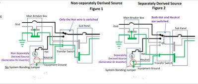
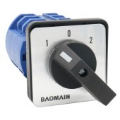
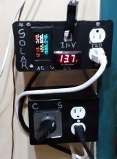
I have a 120vac inverter from my solar going to a dp on-off-on manual transfer switch. The commercial hot and neutral are isolated from the inverter hot and neutral. The output of the switch goes to one 120 volt receptacle that my computer plugs in to. My question is should I tie the ground from the inverter and commercial power ground both to the ground connection on the recepticle or should the grounds be switched also?
 
The wiring method I used is "separately derived source" (fig.2). The only difference is that I have a standard receptacle in place of the sub panel. My inverter is also grounded to the solar system earth rod and my inverter connects ground and neutral together inside the inverter. Am I still correct in using the the diagram in fig. 2 ?
 

Attachments

  • Grounding.jpeg
    Grounding.jpeg
    104.9 KB · Views: 25
If I’m reading this right - your inverter is internally bonded then you don’t want it connected in any way to the powerco ground rod or any other subpanel or outlet bare/green/ground.
 
You want all three conductors to be pure to their source. You don’t want the possibility of neutral feeding the bare/green/ground.

Your inverter is apparently described in figure two because your inverter is internally bonded.

Therefore you have connected according to the instructions which is correct.

The bare/grn/ground going to a bonded panel is the question; your inverter should not need to be ‘grounded’ beyond itself and I would think a 3-wire transfer switch would deal with any issue.

Probably a licensed electrician or one of the wise chairs should explain the NEC on that.
That was what I was thinking until I ran across this wiring diagram. I haven't hooked the commercial power up yet. Just using the inverter off my small solar system. I will look for a three-pole manual transfer switch before I go any further. Thanks
 
From my inverter manual:
"6. CONNECTION
1). Grounding
The power inverter has a terminal on the back panel marked "Grounding" or "
".
This is used to connect the chassis of the power inverter to the ground.The ground
terminal has already connected to the ground wire of AC output receptacle through
the internal connecting wire. The ground terminal must be connected to the ground
wire, which will vary depending on where the power inverter is installed. In a
vehicle, connect the ground terminal to the chassis of the vehicle. On the ship,
connect the ground terminal to the ship grounding system; In a fixed position,
connect the ground terminal to the earth."
 
I would keep it holy and pure and not use the entrance service panel to ‘ground’ it then. I would drive a new rod. To comply with instructions.

To comply with my head I would not connect it to ground rod myself especially after the mike holt video exchanged here recently. But don’t do what I do - learn and make your own decision about that.
 
Don't know about the video you speak of. Can you link the location of it?
 
Got me a 30 amp rated drum switch. I am now switching ground, neutral and hot on my 120 volt circuit. Position 1 is commercial power, center is off, position 2 is solar. Solar is now completely isolated from commercial power. Everything I want to power is now connected. I've been running everything 24 hours a day for the last four days. My battery voltage has never gotten below 12.6 volts so far. The max I've seen it draw is about 1.5 amps when both computers are booting up. Then it drops to around .85 amp. So far so good.
 

Attachments

  • switch.jpg
    switch.jpg
    67.6 KB · Views: 2
  • controls.jpg
    controls.jpg
    233.1 KB · Views: 2
The wiring method I used is "separately derived source" (fig.2). The only difference is that I have a standard receptacle in place of the sub panel. My inverter is also grounded to the solar system earth rod and my inverter connects ground and neutral together inside the inverter. Am I still correct in using the the diagram in fig. 2 ?

No. Do not switch the Equipment Grounding conductor.

If I follow your description, this is what you have:

1645766051495.png

The problem I see with this is that there are two earth grounds at separate points on the Equipment Grounding Conductor system.
This can be a problem in a storm.

1645766241489.png
 
problem I see with this is that there are two earth grounds
To comply with my head I would not connect it to ground rod myself
I appreciate so much the learning on this forum. Fast answers, information to back it up. Not mere opinions like some electricians in my past with extra ground rods wherever they tied something.
 
No. Do not switch the Equipment Grounding conductor.

If I follow your description, this is what you have:

View attachment 85197

The problem I see with this is that there are two earth grounds at separate points on the Equipment Grounding Conductor system.
This can be a problem in a storm.

View attachment 85198
That is what I HAD. It is no longer what I have. I no longer have my inverter tied to a separate grounding rod. My equipment ground on the inverter circuit now stops at the inverter. I switch all three (hot, neutral and eq.ground). My 120 volt receptical is now completely isolated from the commercial power system when switched to solar power.
 
MHSO. You should always switch both 'hot' and 'neutral' in the transfer switch. You should not switch the 'earth' in the transfer switch. You should not have a second 'earth rod' from the inverter. The case is the 'earth' reference. It will do no harm to have all the 'earth' common to the system.
Use diagrame 2, separate sources, to wire your system. The diagram you linked, not the diagram FilterGuy linked. You do not want a second earth rod connection in the ac circuit. It is ok to have a earth rod connection to the metal frame work of non-movable solar panel mounting.
 
You should always switch both 'hot' and 'neutral' in the transfer switch.
Are you saying this in reference to a particular inverter or are you saying you should always switch neutral no matter what?

The reality is that in some cases, you should not switch neutral and in other cases, you should switch neutral. It all depends on the particular installation and the inverter(s) being used.
 
The way it's wired now is how it would be in a stand alone off grid solar system. It is totally isolated from anything in the commercial power system. I'm going to leave it this way.
 
Back
Top