


You are using an out of date browser. It may not display this or other websites correctly.
You should upgrade or use an alternative browser.
You should upgrade or use an alternative browser.
Growatt 48v 3000 Open Neutral
- Thread starter jkp
- Start date
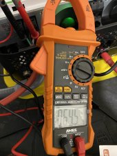
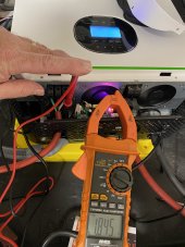
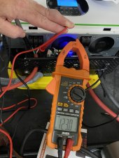
Using Growatt SPF3000. Tried option 24 with both enabled and disabled (unplugged from grid). Results the same. Ground to neutral is always 64v and Ground to Hot is always 55v. Something seems wrong.
Attachments
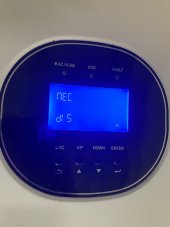
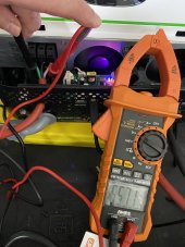
Tried with it plugged into grid. Option 24 toggled did nothing but different behavior on grid. Ground to Neutral is 1.85v but Ground to Hot was 120v.Using Growatt SPF3000. Tried option 24 with both enabled and disabled (unplugged from grid). Results the same. Ground to neutral is always 64v and Ground to Hot is always 55v. Something seems wrong.
Attachments
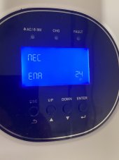
Just click through till you get to 24. Didn’t do anything regardless. I am concerned that we’re both getting similar readings when on battey across neutral/ground and ground/hot.How did you get to Option 24, it's not (seemingly) on my 3000.
tigerwillow1
Solar Enthusiast
- Joined
- Sep 20, 2021
- Messages
- 194
"open neutral" is an interpretation. What it really means is there is little or no continuity between ground and neutral, when it should be close to a dead short. The ground or neutral is floating. Notice that the sum of hot-to-neutral plus ground-to-neutral is always nominal 120 volts. As an experiment, try connecting ground and neutral together with a low-watt incandescent light bulb (acting as a fuse). I'd expect the error to go away.
@tigerwillow1 I don’t think the OP or I have an error, just noticing the same behavior. Not sure I have an easy way to test what you propose but you think this is working as expected?"open neutral" is an interpretation. What it really means is there is little or no continuity between ground and neutral, when it should be close to a dead short. The ground or neutral is floating. Notice that the sum of hot-to-neutral plus ground-to-neutral is always nominal 120 volts. As an experiment, try connecting ground and neutral together with a low-watt incandescent light bulb (acting as a fuse). I'd expect the error to go away.
Ground to neutral is always 64v and Ground to Hot is always 55v
It's not on my menu via normal or standby modes so perhaps my firmware does not have it presented.Just click through till you get to 24. Didn’t do anything regardless. I am concerned that we’re both getting similar readings when on battey across neutral/ground and ground/hot.
As I understand it Option 24 controls a relay on the underside of the unit. You can leverage this relay to control a downstream relay to either close or open a contact for neutral bonding.Tried with it plugged into grid. Option 24 toggled did nothing but different behavior on grid. Ground to Neutral is 1.85v but Ground to Hot was 120v.
Here is a video that shows this.
I just can't get to the option to test this.
Agreed, just can find how to get to the option. LOLI think you need to leverage the dry contactor relay (3amp max) on the bottom connected to a larger relay handling the neutral bonding duties when running on battery. I‘ve upgraded my Growatt‘s firmware (same as yoursj but option 24 doesn’t exist.
tigerwillow1
Solar Enthusiast
- Joined
- Sep 20, 2021
- Messages
- 194
Somewhere along the line of reading through the thread I invented that you were seeing an error message. Sorry 'bout that. Let me start over.@tigerwillow1 I don’t think the OP or I have an error, just noticing the same behavior. Not sure I have an easy way to test what you propose but you think this is working as expected?
The reasons given for abnormal indications on the 3-light tester are "probable" causes, not necessarily the real causes. "Open neutral" is a common false diagnosis, when the actual cause of the abnormal indication is the lack of a neutral-ground bond, especially when the power source is not the grid. IMO, the lack of a neutral-ground bond is the likely reason you're seeing the abnormally high voltage between neutral and ground. It looks like you're using the inverter ground lug as the ground reference, which means earth ground isn't a factor and may or may not be an additional issue. Not being familiar with your specific inverter makes it risky for me to make specific statements, so as a general statement I'll say I'm surprised that the transfer relay in the inverter isn't creating the neutral-ground bond. Some inverters have an option to enable or disable this function. If the inverter doesn't have any provision for the neutral-ground bond it's a design deficiency, and its use doesn't meet NEC requirements in the USA.
One solution would be to hardware the inverter input and output neutrals together so your main panel neutral-ground bond is always carried to the inverter output. I cannot say if this would meet the NEC requirement or cause any harm to the inverter. It's one of those things where if you polled a lot of electricians you might well get a 50-50 split on opinions. The relay solution a few posts up is a more correct solution, code wise, but introduces another device that could fail down the road. So I will pass on firmly stating the correct way to solve the problem and restate the solution should have been built into the inverter.
The light bulb procedure I mentioned is just to confirm the lack of neutral-ground bond diagnosis without the risk of burning something up. If the problem is actually just a floating neutral, it can be connected to the ground wire with no bad consequences. With no loads on the AC output, if you connect the light bulb between neutral and ground, and no meaningful current is flowing as confirmed by darn close to zero volts across the light bulb, it follows that there's no short circuit created by connecting neutral to ground. If the light bulb doesn't pull the neutral-ground voltage to near zero, there's a different issue in play and it's back to the drawing board.
@tigerwillow1 @jkp I just ran my GW SPF3000 48v through my transfer switch that use for my generator. Activated a few circuits in house and tested. All was perfectly fine from ground/neutral perspective using a tester. Must be since ground and neutral are connected from TS to main panel. Pretty awesome.Somewhere along the line of reading through the thread I invented that you were seeing an error message. Sorry 'bout that. Let me start over.
The reasons given for abnormal indications on the 3-light tester are "probable" causes, not necessarily the real causes. "Open neutral" is a common false diagnosis, when the actual cause of the abnormal indication is the lack of a neutral-ground bond, especially when the power source is not the grid. IMO, the lack of a neutral-ground bond is the likely reason you're seeing the abnormally high voltage between neutral and ground. It looks like you're using the inverter ground lug as the ground reference, which means earth ground isn't a factor and may or may not be an additional issue. Not being familiar with your specific inverter makes it risky for me to make specific statements, so as a general statement I'll say I'm surprised that the transfer relay in the inverter isn't creating the neutral-ground bond. Some inverters have an option to enable or disable this function. If the inverter doesn't have any provision for the neutral-ground bond it's a design deficiency, and its use doesn't meet NEC requirements in the USA.
One solution would be to hardware the inverter input and output neutrals together so your main panel neutral-ground bond is always carried to the inverter output. I cannot say if this would meet the NEC requirement or cause any harm to the inverter. It's one of those things where if you polled a lot of electricians you might well get a 50-50 split on opinions. The relay solution a few posts up is a more correct solution, code wise, but introduces another device that could fail down the road. So I will pass on firmly stating the correct way to solve the problem and restate the solution should have been built into the inverter.
The light bulb procedure I mentioned is just to confirm the lack of neutral-ground bond diagnosis without the risk of burning something up. If the problem is actually just a floating neutral, it can be connected to the ground wire with no bad consequences. With no loads on the AC output, if you connect the light bulb between neutral and ground, and no meaningful current is flowing as confirmed by darn close to zero volts across the light bulb, it follows that there's no short circuit created by connecting neutral to ground. If the light bulb doesn't pull the neutral-ground voltage to near zero, there's a different issue in play and it's back to the drawing board.
FilterGuy
Solar Engineering Consultant - EG4 and Consumers
All, I am late to this thread.... but here is my 2 cents:
If you would like to understand Neutral-ground bonding better, you may want to review the 4 Grounding resources that start with this one:

 diysolarforum.com
This resource gives details of grounding for several popular inverters (Including Growatt and the external relay):
diysolarforum.com
Look for an option that talks about controlling the dry contact. BTW: What is the exact model of your inverter?
@jkp In your original post, you show a diagram with the ground being switched and two separate grounding rods. I would never do either of those. The system should have a single point where it ties to earth ground and the grounding conductors should never be switched.
If you would like to understand Neutral-ground bonding better, you may want to review the 4 Grounding resources that start with this one:
Grounding Made simpler - Part 1: AC/houshold grounding
To get the paper, click on the orange button at the top of the screen. The subject of grounding is a complex, multifaceted subject, that is often treated as an after-thought but needs to be considered from the beginning of the design and build...
diysolarforum.com
This resource gives details of grounding for several popular inverters (Including Growatt and the external relay):
Grounding details for specific make/model of inverters
To get to the paper, click on the orange button at the top of the screen. It is important to understand how an inverter handles grounding in order to set it up correctly. Unfortunately, many inverters do not provide adequate documentation on...
diysolarforum.com
That is a good video about the Growatt external grounding relay.... but despite the author's assertion that the relay he is using is big enough, it is not. The purpose of the N-G bond is to carry fault current in the event of a short between hot and the Ground wire. Therefor the bond must be able to take the full current of the inverter. For a 3000W inverter that is 25A. (He may get away with the 10A relay because the short circuit current would quickly blow the breaker so the high current is for a very short period).As I understand it Option 24 controls a relay on the underside of the unit. You can leverage this relay to control a downstream relay to either close or open a contact for neutral bonding.
Here is a video that shows this.
I just can't get to the option to test this.
I vaguely remember some of the older models with older firmware had the option as a different number. (I am remembering option 14 but that could be wrong)Agreed, just can find how to get to the option. LOL
Look for an option that talks about controlling the dry contact. BTW: What is the exact model of your inverter?
@jkp In your original post, you show a diagram with the ground being switched and two separate grounding rods. I would never do either of those. The system should have a single point where it ties to earth ground and the grounding conductors should never be switched.
Could you provide a diagram of the system you have?I just ran my GW SPF3000 48v through my transfer switch that use for my generator. Activated a few circuits in house and tested. All was perfectly fine from ground/neutral perspective using a tester. Must be since ground and neutral are connected from TS to main panel. Pretty awesome.
All, I am late to this thread.... but here is my 2 cents:
If you would like to understand Neutral-ground bonding better, you may want to review the 4 Grounding resources that start with this one:
Grounding Made simpler - Part 1: AC/houshold grounding
To get the paper, click on the orange button at the top of the screen. The subject of grounding is a complex, multifaceted subject, that is often treated as an after-thought but needs to be considered from the beginning of the design and build...
This resource gives details of grounding for several popular inverters (Including Growatt and the external relay):
Grounding details for specific make/model of inverters
To get to the paper, click on the orange button at the top of the screen. It is important to understand how an inverter handles grounding in order to set it up correctly. Unfortunately, many inverters do not provide adequate documentation on...
That is a good video about the Growatt external grounding relay.... but despite the author's assertion that the relay he is using is big enough, it is not. The purpose of the N-G bond is to carry fault current in the event of a short between hot and the Ground wire. Therefor the bond must be able to take the full current of the inverter. For a 3000W inverter that is 25A. (He may get away with the 10A relay because the short circuit current would quickly blow the breaker so the high current is for a very short period).
I vaguely remember some of the older models with older firmware had the option as a different number. (I am remembering option 14 but that could be wrong)
Look for an option that talks about controlling the dry contact. BTW: What is the exact model of your inverter?
@jkp In your original post, you show a diagram with the ground being switched and two separate grounding rods. I would never do either of those. The system should have a single point where it ties to earth ground and the grounding conductors should never be switched.
Could you provide a diagram of the system you have?

@FilterGuy I don’t have a diagram for home, just testing for a permanent solution for my cabin, which I may also use this transfer switch configuration. The short story is, you wire up neutral, ground and hot(s) from TS to panel. You can then select if you want to run off grid or generator/inverter in my case by individual circuit. Today I hooked up inverter to generator receptacle, flipped circuits in TS I wanted to test with inverter and tested them with ground fault tester. All were perfect. I then ran inverter at 99.5% to test load on it using space heaters on two different legs of TS to get to 3000w. I have a jumper between XY in my LR-14 plug to power both sides of switch, no 240 loads.
Top-Quality Transfer Switch Kit | Reliance Controls
We provide top-quality generator transfer and safety switch, generator transfer panel, power transfer switch for generator, and house generator transfer switch.
FilterGuy
Solar Engineering Consultant - EG4 and Consumers
Does it all test out ok if the system is not plugged into the grid AC wall socket?@FilterGuy I don’t have a diagram for home, just testing for a permanent solution for my cabin, which I may also use this transfer switch configuration. The short story is, you wire up neutral, ground and hot(s) from TS to panel. You can then select if you want to run off grid or generator/inverter in my case by individual circuit. Today I hooked up inverter to generator receptacle, flipped circuits in TS I wanted to test with inverter and tested them with ground fault tester. All were perfect. I then ran inverter at 99.5% to test load on it using space heaters on two different legs of TS to get to 3000w. I have a jumper between XY in my LR-14 plug to power both sides of switch, no 240 loads.
Top-Quality Transfer Switch Kit | Reliance Controls
We provide top-quality generator transfer and safety switch, generator transfer panel, power transfer switch for generator, and house generator transfer switch.www.reliancecontrols.com
Sure did. Ground/Neutral check not connected to grid was the main reason for test as well as battey load test.Does it all test out ok if the system is not plugged into the grid AC wall socket?
FilterGuy
Solar Engineering Consultant - EG4 and Consumers
I don't know the details of how it is all wired, but if it tests correctly both when plugged into the grid and not plugged into grid, and it is a Growatt inverter, there are probably two Neutral - Ground bonds when plugged into the grid. To test this, put a load on the system when being powered by the grid and see if there is current on the ground wire. (If there are two N-G bonds, the ground wire will have ~1/2 the current from the load).Sure did. Ground/Neutral check not connected was the main reason for test as well as battey load test.
Current on the ground wire is a big safety no-no and it will not be caught by the simple 3-LED testers.
@FilterGuyI don't know the details of how it is all wired, but if it tests correctly both when plugged into the grid and not plugged into grid, and it is a Growatt inverter, there are probably two Neutral - Ground bonds when plugged into the grid. To test this, put a load on the system when being powered by the grid and see if there is current on the ground wire. (If there are two N-G bonds, the ground wire will have ~1/2 the current from the load).
Current on the ground wire is a big safety no-no and it will not be caught by the simple 3-LED testers.
Trying to think how to test this. I will basically have the grid feed a circuit through my inverter and through my transfer switch. Should I put this in UTIL or SBU mode?
FilterGuy
Solar Engineering Consultant - EG4 and Consumers
Put it in Utility First mode

@FilterGuy
So that was an interesting test.
Baseline on Grid completely: No open ground from tester and can see 122v across Ground and Hot, same 122v with Neutral and Hot. Neutral and ground was 0.31v
Battery Only from Inverter: No open ground from tester and can see 118v across Ground and Hot, same 118v with Neutral and Hot. Neutral and ground was 0.23v
Grid Through Inverter UTIL mode: UNTESTABLE. GFCI in garage where inverter plugged into popped immediately, regardless if Transfer switch was set to Gen/Inverter, OFF, or Line/Grid for the circuit being tested.
Thoughts?
Similar threads
- Replies
- 6
- Views
- 268
- Replies
- 27
- Views
- 874
- Replies
- 3
- Views
- 317