sunshine_eggo
Happy Breffast!
Claim:
What theory? Yours?
Cite source or confirm you just made it up.
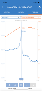
To find the same for a battery with multiple cells in series, discharge with rated constant current, until one of the Cell hits 2.5 V. Then note the voltage of that cell after recovery. That in theory, represents the absolute minimum cut-off voltage for LFP.
I don't have the money and equipment to test it with factory new cells, but I suppose it is somewhere around the ~2.8V mark.
What theory? Yours?
Cite source or confirm you just made it up.