diy solar

diy solar

GUIDE to properly Top-Balance and Charge a LFP Battery: Part 1

But if you send a stop charging (to where? the charge controller? what protocol?) you now don't harness any solar anymore for your loads.
I meant that in the case of All in One Inverters switching to float at the end of charge cycle.
Of course, one only wants the power going into the battery to stop, never the loads.
 
I found this Off Grid Garage video to be interesting .... Especially since I am trying out the JK BMS.

 
Breaking news: you are all charging the wrong way. ;-)

Sensationalism aside, some things have changed in the newest datasheet for EVE LF280K.

In older datasheets standard charge is said to be "Charging the cell with charge current 0.5C(A) and constant voltage 3.65V at(25±2)℃, 0.05C cutoff." In other words constant current, then constant voltage with a tail current cutoff.

If you look at the latest datasheet all charge rates are now specified in terms of power, not current. 0.5C became 0.5P. Which means that a constant power charge will taper the current off slightly when the cell approaches 100% SOC, because the voltage rises at that point. This is of course not possible to with 99% of solar chargers, because they only have settings for constant current, not constant power.

The most important change is that it seems like the EV industry has dropped the idea that a standard charge involves monitoring tail current. There is no mention of it at all. Standard charging is simply constant power charging to 3.65V. This is a simpler model to get to 100% SOC.


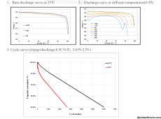
Section 3.8.3.7. 25℃ Standard Cycle

Section 3.8.3.8. Cycle Recommended By EVE.
 
I found this Off Grid Garage video to be interesting .... Especially since I am trying out the JK BMS.

Extremely Perfect charging solution, Lithium charging done and dusted !! No need to bother with anything else.
Battery woes will be a thing of the past.
Now they will be your future!
 
Last edited:
Breaking news: you are all charging the wrong way. ;-)

Sensationalism aside, some things have changed in the newest datasheet for EVE LF280K.

In older datasheets standard charge is said to be "Charging the cell with charge current 0.5C(A) and constant voltage 3.65V at(25±2)℃, 0.05C cutoff." In other words constant current, then constant voltage with a tail current cutoff.

If you look at the latest datasheet all charge rates are now specified in terms of power, not current. 0.5C became 0.5P. Which means that a constant power charge will taper the current off slightly when the cell approaches 100% SOC, because the voltage rises at that point. This is of course not possible to with 99% of solar chargers, because they only have settings for constant current, not constant power.

The most important change is that it seems like the EV industry has dropped the idea that a standard charge involves monitoring tail current. There is no mention of it at all. Standard charging is simply constant power charging to 3.65V. This is a simpler model to get to 100% SOC.


Section 3.8.3.7. 25℃ Standard Cycle

Section 3.8.3.8. Cycle Recommended By EVE.
Time to edit my posts :p
They must now pave way for Standard Power Model Supremacy. :)

Interestingly, The claimed cycle life has stayed the same at 6000 cycles before 80% SOH. No reasons the underlying chemistry has changed much.
Cycle Recommended By EVE
Preparation for the fixture: When the SOC is 30%~40% at room temperature, install the test fixture according to the methods in (3.4). 30%~40% SOC 3.4 Cycle test: at ambient temperature of 25℃±2℃;

a. Discharge the battery in accordance with (3.6);
b. Charge the battery to 3.6V with a constant power of 448W;
c. Charge the battery to 3.65 V with a constant power of 44.8W and rest for 30minutes;
d. Discharge to 2.5 V at a constant power of 448W and rest for 30minutes;
e. Repeat steps b~d.

When the battery is at 80% SOH and 70% SOH, modify the charging and discharging power according to the energy of the battery:


100-80%SOH80-70%SOH70-60%SOH
448W358.4W313.6W
0.5 P0.4 P0.35 P
Extremely interestingly, the datasheet also supplies charge/discharge curves. (I've having a bit of trouble spotting voltages higher than 3.4 V :p)

EVE CElls.png

All real world Solar scenarios don't need to bother with power because most installations are going to be below 0.5 P anyway.

Now, I'm interested in someone makes a video subjecting a brand new EVE Cell to
Charge the battery to 3.6V with 0.5 P;
And report the resulting OCV at rest.
 
Last edited:
Extremely interestingly, the datasheet also supplies charge/discharge curves. (I've having a bit of trouble spotting voltages higher than 3.4 V)

I only found discharge curves - where did you see charge curves? It's normal for the discharge curves to be below 3.4V since under load the voltage drops very quickly to that point.
 
I found this Off Grid Garage video to be interesting .... Especially since I am trying out the JK BMS.


Interesting product, I hope it gets popular. Can probably make a big difference for people with a charger that isn't very configurable. Can it connect to more than one BMS at a time? Also, they should probably add some more charge control methods, like tail current and constant power.

I will probably be building my own version of this, because I already have an Arduino that monitors my system.
 
IMG_0907.gif

So if one chooses to ignore tail current for the time being and desires a “fully charged pack” to be cells at 3.55v let’s go back a moment to some discussion referencing @toms as well as @upnorthandpersonal

If I understand correctly, it would be appropriate when commissioning a set of cells into a pack to individually charge each cell to 3.45v prior to placing them in a pack. At that point with each cell charged within .01v, one could complete battery assembly and allow the cells to “self equalize” or “top off” the pack as a whole? Is that a fair assessment?
After 24-48hrs one could take measure of each cell to compare voltage drop to determine performance limits of the pack as a whole?

Am I completely missing the mark? This is a fascinating conversation regardless of humility/arrogance/name calling etc. it seems there’s a lot of brain power in here that I need to catch up on.
I am an actual chemist but have no working knowledge of Lifepo4 properties ?
 
Does anybody wonder why UL1973 & UL9540A certified battery manufacturers are deliberately holding cells at > 3.45V all day, claiming 4000 cycle life and offering 10 year warranties?
I’ve seen the target voltage for “full” cells fall from 3.65 to as little as 3.35 for some commercial BMS’ over the decade i’ve been using these cells. I don’t wonder why that has happened - i know it is because manufacturers have seen evidence of reduced lifespan due to lithium plating from cells held at higher voltages.
 
View attachment 181721

So if one chooses to ignore tail current for the time being and desires a “fully charged pack” to be cells at 3.55v let’s go back a moment to some discussion referencing @toms as well as @upnorthandpersonal

If I understand correctly, it would be appropriate when commissioning a set of cells into a pack to individually charge each cell to 3.45v prior to placing them in a pack. At that point with each cell charged within .01v, one could complete battery assembly and allow the cells to “self equalize” or “top off” the pack as a whole? Is that a fair assessment?
After 24-48hrs one could take measure of each cell to compare voltage drop to determine performance limits of the pack as a whole?
Unless you charge the cells into their voltage knee you will not know if they are at the same SOC.

There is no issue charging the cells to 3.65V as long as you use a high enough current to prevent the cell from being full.

I think the important thing to remember is that for any given voltage, the lower the charge current the higher the SOC will be. And once the battery reaches 100% SOC (no more room in the anode for lithum intercalation), if there is still a charge current you will start lithium plating.

Well written summary.
 
I’ve seen the target voltage for “full” cells fall from 3.65 to as little as 3.35 for some commercial BMS’ over the decade i’ve been using these cells. I don’t wonder why that has happened - i know it is because manufacturers have seen evidence of reduced lifespan due to lithium plating from cells held at higher voltages.

When in BMS comms with a charger, SOK, Pylontech, etc. all charge to and hold at about 3.5V like one would charge NCA/NCM/LMO, i.e., two phase charging... CC/CV, no float. In other words, they are all essentially overcharging by holding 3.5V at 0A.

If low current over charge results in lithium plating, these batteries are deliberately engaging in conditions that encourage lithium plating for hours on a daily basis.

IMHO, most of this business is picking fly turds out of pepper. When LFP was introduced, it was charge to 4.2V and discharge to 2.0V, and well... things didn't go so well. You'd get about 10% more, but there was a lot of stress to the cells resulting in the disappointment of the unwashed masses seeing their cycle life go to shit.

15 years pass... take those same cells and make incremental improvements to them over that time. Narrow their operating range, losing 10% capacity, but making large gains in cycle life.

So, we've gone from charging to 4.2V/X Amps tail current to charging to 3.45-3.65V at 0A tail current. Avoiding high current in the knees shows promise for further stress reduction/cycle life increase.
 
Last edited:
Wow, for this beginner this thread has blown what little grey matter I had left to scrambled egg.
So simple question. Should I be setting a tail current of 3.4A for my 340ah battery on the victron smart solar MPPT App Victron connect, or should I be leaving it disabled which is the default setting?
 
Back
Top