diy solar

diy solar

Help/Critique of RV System, Wire/Connectors

That Lynx Power In is just a glorified bus bar. The upper scale model has fuse mounts and monitoring.
This is what I used: 250A per post, 4 posts
Also, most of the current will circulate between battery and inverter/converter. I would run inverter/converter positive directly to the cutoff switch, and the negative to the shunt. Hint: Both the Shunt and the switch can have 2 wires on terminals.
 
Last edited:
The negative on this DC-DC converter is not a load power return. It's a reference and power for the converter. I would tie it to the neg busbar. I would also tie the 12v load return to the neg busbar.
Thank you! I'll make that change. So what happens to the 12V negative?
Add heat shrink tubing to your shopping list. The good stuff has adhesive on the inside.
Thanks! I'll be spending a lot of time now trying to figure out the lug sizes and wire lengths. This is time consuming!
 
That Lynx Power In is just a glorified bus bar. The upper scale model has fuse mounts and monitoring.
This is what I used: 250A per post, 4 posts
Also, most of the current will circulate between battery and inverter/converter. I would run inverter/converter positive directly to the cutoff switch, and the negative to the shunt. Hint: Both the Shunt and the switch can have 2 wires on terminals.
Thanks, that's what I was using it as, for a clean layout with a nice cover. I felt I didn't need the Distributor version as I was using circuit breakers that would do double duty as switches.

I'll consider the possibility of having two wires on some terminals. I was worried the Lynx Power In wouldn't have space for two wires per slot. Are those little tunnels fairly roomy?
 
Last edited:
Thank you! I'll make that change. So what happens to the 12V negative?

Thanks! I'll be spending a lot of time now trying to figure out the lug sizes and wire lengths. This is time consuming!
12v negative goes back to the source, be it battery or converter.
 
Looks like the inverter/converter has a pair of high current studs for pos and neg.
victron 24v example
The case ground is your typical AC green grounding wire. It's not a heavy DC wire gauge.

Bad News: The starter trickle charge voltage will not be 12v, with 24v coach battery setting.
manual page 3
 
Last edited:
Bad News: The starter trickle charge voltage will not be 12v, with 24v coach battery setting.
manual page 3
holy shit you're right. just tested it and it's the same voltage as the main battery. good thing my multiplus is still on the floor and not installed otherwise I would have seen some fireworks
 
Warning: Be careful what circuit breakers, switches, and fuses you use for DC solar.
DC is used for ARC Welding. AC passes thru Zero Volts and may extinguish an ARC.
Many DC circuit breakers are rated for 48V max. Like the Blue Sea 187s mentioned.
Consider using MC4 fuses for the 3 panels strings. More than 2 parallel strings should get fused.
MC4 Fuse example
 
Last edited:
Thanks for bringing this up!

I was calculating based on the rating of 3000W, which would be 125A at 24V. I checked the manual, and for the 24|3000-70 (vs the 12|3000) it recommends 50mm (1/0) for under 5 m runs, two for 50mm cables for 5-10m. My battery will be less than 1.5 m from the Multiplus, so 1 cable should suffice, but I should upgrade it to 1/0 from 2 AWG. (The 24|3000-70's peak power rating is 6000W, or 250A, so while that should only last a few seconds at a time, 1/0 is definitely a safer bet.)

The manual also recommends a 300A fuse. I'd like to upsize from a 200A breaker to a 300A, but I only see no-name Chinese breakers rated at 300A; Blue Sea only seems to go to 200A. Any suggestions on high quality circuit breakers good for 300A?
Nice i’m glad i could help :) i’m planing a very similar system so your process and changes are a great read for me
 
Maybe something to simplify your layout:
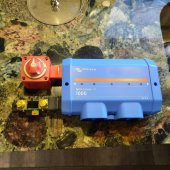
I just bought a Lynx "power in" (going to use it as a distributor) to clean up my instalation ... I plan on bolting the main switch and the shunt direct to its (very beefy) busbars to cut down on wiring/lugs .... im also going to convert it to a distributor by adding the missing bolts that allow you to add mega fuses ?
Pic is just a mockup... need to enlarge the holes in the busbars to bolt them up
20210519_054721.jpg
 
Last edited:
Maybe something to simplify your layout:
I just bought a Lynx "power in" (going to use it as a distributor) to clean up my instalation ... I plan on bolting the main switch and the shunt direct to its (very beefy) busbars to cut down on wiring/lugs .... im also going to convert it to a distributor by adding the missing bolts that allow you to add mega fuses ?
Pic is just a mockup... need to enlarge the holes in the busbars to bolt them up
View attachment 49598
I'm doing the exact same setup with my Lynx distributer with switch and shunt mounted direct to the bus bars.

Good move on getting the power in and adding the hardware for the fuses. I didn't realize that was an option when I bought the lynx distributer, so that was a bit of a waste of $ for the electronics I don't need.
 
Maybe something to simplify your layout:
I just bought a Lynx "power in" (going to use it as a distributor) to clean up my instalation ... I plan on bolting the main switch and the shunt direct to its (very beefy) busbars to cut down on wiring/lugs .... im also going to convert it to a distributor by adding the missing bolts that allow you to add mega fuses ?
Pic is just a mockup... need to enlarge the holes in the busbars to bolt them up
View attachment 49598
I've seen others using those busbar M8 holes for other things. It's genius! I did't realize all I needed was M8 bolts and nuts. Love it for simplicity, worry about physical rigidity. I hope I won't need to disconnect the attached switch and shunt!
 
I just found the Blue Sea Systems HD Series 3000 battery switch actually has two output terminals plus 600A rating. Wondering if I could use M8 hardware to fix one output to the Lynx Power In busbar and the other direct to the MultiPlus, freeing up the Power In’s output terminals.

And combining @Screwball and @Pappion’s suggestions I would attach the Smart Shunt and the MultiPlus battery negative and case ground to the negative busbar.

And to further simplify the system I could use the driver tying my Overkill BMS into the Victron GX monitoring system, though it adds the serial connection as a component. But if I do that, should the BMS crap out I would have no working battery monitoring.
 
Maybe something to simplify your layout:
I just bought a Lynx "power in" (going to use it as a distributor) to clean up my instalation ... I plan on bolting the main switch and the shunt direct to its (very beefy) busbars to cut down on wiring/lugs .... im also going to convert it to a distributor by adding the missing bolts that allow you to add mega fuses ?
Pic is just a mockup... need to enlarge the holes in the busbars to bolt them up
View attachment 49598
Hey @Screwball, I was just biting your idea but my photo of the Smart Shunt shows the "To System Minus" and "To Battery Minus" posts reversed from your mockup. Can you please confirm you have the system minus attached to the neg bus bar? I'm not at home so I can't check mine.
 
The negative on this DC-DC converter is not a load power return. It's a reference and power for the converter. I would tie it to the neg busbar. I would also tie the 12v load return to the neg busbar.
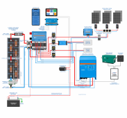
Would this work? I tied the 12V load center neg to the neg terminal of the 24-12V converter and ran another line from same terminal to busbar.

I also made the following changes:
1. …incorporated your idea of tying the inverter leads directly to the battery switch and shunt (and using two cables per terminal) to leave more room on the busbars;
2. I also bolted the battery switch directly to the Lynx Power In's busbar per @Screwball;

Those changes allowed me to get rid of the mini busbars and STILL have room for a future item, possibly another solar charger for portable solar panels.

I also added an Amp-L-Start as trickle charger for the 12V chassis battery since the MultiPlus's trickle charger is basically 25.6V. I used the two wire trick to run 12V + leads from the 24-12V converter to both the 12V load center and the Amp-L-Start.

Thanks for your help, @Pappion, @Screwball, and everyone else who contributed suggestions! This system is a LOT leaner, cleaner, but still very capable thanks to all your input.

Winnebago Via Electrical Solar Wiring Diagram Lynx 2021-05-21.png
 
Hey @Screwball, I was just biting your idea but my photo of the Smart Shunt shows the "To System Minus" and "To Battery Minus" posts reversed from your mockup. Can you please confirm you have the system minus attached to the neg bus bar? I'm not at home so I can't check mine.
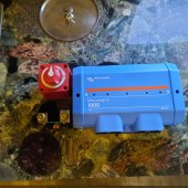
Here is the finished setup .... holes are east to enlarge with a quality step drill (its solid copper) ... shunt is in the right position according to the stamping on the terminals... need to double check ?

20210519_184532.jpg
 
I think your multiplus should be connected to busbar and not the switch terminal ?!?
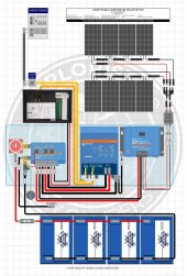
I'm going with a layout very close to this one by Nate at Explorist (mega fuses added to the lynx):

Screenshot_20210513-055538_Facebook.jpg
 
Here is the finished setup .... holes are east to enlarge with a quality step drill (its solid copper) ... shunt is in the right position according to the stamping on the terminals... need to double check ?

View attachment 49865
If yours is stamped that way it’s definitely right. I just have the high res photo I downloaded from Victron that is labeled differently, maybe a preproduction unit or Photoshopped in by their artists?
 
I think your multiplus should be connected to busbar and not the switch terminal ?!?
I'm going with a layout very close to this one by Nate at Explorist (mega fuses added to the lynx):

View attachment 49867
Functionally speaking there’s no need to be on the busbar, but I have an empty spot in the busbar and it would look cleaner if I moved it onto the busbar.
 
Back
Top