I am not familiar with your charger, but yes, sort of, is my answer.
Your absorb voltage should be about 3.5 volts per cell for a full charge, or just 3.4 volts if you want to extend the life a bit. That is still very close to truly full on LFP cells. Once the absorb charge stage ends, most just have the charger shut off. But if you have a separate charge controller, or an "all in one" that is charging from the sun, and inverting to power loads, then you want to keep the solar providing the power. This is done by using a float charge setting. The float voltage should be a little below where the cells would rest at a very small load. Most LFP cells seem to drop down about 0.2 volts when the charge current is cut off. So take whatever you set your absorb voltage to, and drop it by about 0.2 to 0.3 volts per cell to get the float voltage. If you charge to 56 volts (3.5 per cell x 16) then you should have the float between 51.2 and 52.8 volts (3.2 to 3.2 volts per cell). When the cells reach a full absorb charge at 56 volts, the charger will switch to float mode and the current will drop to essentially zero. The inverter will start pulling the voltage down, and the cells will also naturally start to drop back a bit as well. When the voltage drops to the Float Voltage setting, the solar charge source should then start outputting current to hold the battery bank at the float voltage. The current to/from the battery will drop to near zero, and the solar charge controller is essentially running the inverter, with the battery just acting like a capacitor, holding the charge with very little current. This is also a good time for the balancer to do it's job as the battery current is very low.
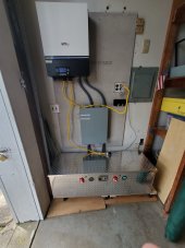
My system can't do this right now as my charger and inverter are the same unit. My only solar source right now is my Enphase system which is AC coupled to the inverter output. The inverter/charger can either take AC current in and charge the battery, or it can take battery current and invert to AC to push into my home, it physically can't do both at once. When I do add some solar panels and a DC coupled MPPT solar charge controller, then I will be able to have it float the batteries and invert like this.