diy solar

diy solar

Home made tracker ideas?

Very cool.

Did you try the diodes and multiple panels yet ?

Yes, the diodes do nothing except get hot. The way this works is the panels have to be fighting to create around a 0 voltage in the center of the wire where the actuator ties in. Once one panel starts to get more sun it will quickly overpower the other, and either drive the voltage at the actuator positive, or negative.

I guess what I'm saying there's never really a time where the diodes aren't in forward bias, so they just get hot, burning energy from the forward voltage drop.

As for the multi panels I have the wood cut, stained, and ready. Just need to assemble, was hoping to do it this weekend. I'll be putting two 435w sunpower panels on it.
 
Diodes came on each of my psnels, are there more that I should know about?
 
Diodes came on each of my psnels, are there more that I should know about?

The diodes on your panels are usually "Bypass" diodes. Those diodes bypass a portion, or even the whole panel depending on the level of shading on it.

The diodes we're talking about here are blocking diodes.
 
@G20

Here's my new PEET tracker with two 435w panels
I like the bevel.

I was thinking about the hinge travel on each side and how to evenly split it in half.

The support board lengths could probably also be split in half to balance the weight (if they aren't already).

Is there any advantage to having the smaller panels on the ends of the larger panel or formed as a pyramid on a single mount on the fulcrum point ? The wires could be shorter but the fulcrum would need to be longer.

Any thoughts on wind resistance ?
 
I like the bevel.

I was thinking about the hinge travel on each side and how to evenly split it in half.

So the max angle I can get is about 30-32 degrees on both sides because if I let it go further It becomes too hard for the actuator to lift it back up.
With that range, maxing out the hinge travel doesn't even come into play.

The support board lengths could probably also be split in half to balance the weight (if they aren't already).

They are fully balanced on the apex of the 2x6. Probably looks off because of the bevel.

Is there any advantage to having the smaller panels on the ends of the larger panel or formed as a pyramid on a single mount on the fulcrum point ? The wires could be shorter but the fulcrum would need to be longer.

That's an interesting thought, hmm. Yeah I guess it would not matter if they form a pyramid off to the right or left side.

One thing they do on the ends is they act as a counterbalance providing leverage to help the actuator lift the panels out of the far west/east 30 degree position

Any thoughts on wind resistance ?

I'm pretty sure the wind is going to take it out at some point in it's current state :) That being said, I have actually had some pretty high winds with the old single panel PEET, and it survived. But now there is more than double the surface area, so...

My thought right now is to build a raised garden under it that the legs will attach to.
 
Here's mine! made out of 2 pallets, wheels from amazon, timber is 38x63mm stud planks, with single slot shelving bars as axles! Bit of strapping screwed underneath, so I can lift and move them around the garden (there are 2 of them).
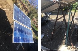
I recommend tying it down to anchors, so when wind comes it doesn't blow over.

Here's mine, after I added tiedowns.
It had blown over into the gas meter, disabling the counter.

panels easle.jpg
 
...

That's an interesting thought, hmm. Yeah I guess it would not matter if they form a pyramid off to the right or left side.

One thing they do on the ends is they act as a counterbalance providing leverage to help the actuator lift the panels out of the far west/east 30 degree position

...
If both sides are equally weighted and spaced, having them on the ends should not give a mechanical advantage. Moving the actuator further away from the fulcrum would give an mechanical advantage at the expense of increased travel.

UPDATE: I see the way that you have them mounted, the high side extends further out and the low side tucks in so it does give a mechanical advantage.

Moving the small panels to the center would take some stress/flex off the panels though.

As for counterbalance, maybe a T in the center ? The weight on the bottom leg of the T would assist in uprighting the T and returning the panels flat similar to a pencil fishing bobber up righting itself.
 
Last edited:
If both sides are equally weighted and spaced, having them on the ends should not give a mechanical advantage. Moving the actuator further away from the fulcrum would give an mechanical advantage at the expense of increased travel.

UPDATE: I see the way that you have them mounted, the high side extends further out and the low side tucks in so it does give a mechanical advantage.

Yes, exactly.

Moving the small panels to the center would take some stress/flex off the panels though.

That's true, probably would need them to stay low though so they keep the counterbalance (bobber effect as you mentioned), and also keep them on the south side.

As for counterbalance, maybe a T in the center ? The weight on the bottom leg of the T would assist in uprighting the T and returning the panels flat similar to a pencil fishing bobber up righting itself.

That's a great idea, I did kind of think about that as the next step if I find it having trouble returning from the far east/west positions. Then wouldn't have to rely on the smaller panels to do that.
 
Using an 18" satellite dish actuator is the way I would go IMHO. I use to have about half a dozen of these and dumped them years ago but they would easily move 6 or more panels at a time. They have limit switches inside and use simple pulse counting for the positioning. Hooked up to an Arduino and two relays and a DIY 24V-36Vdc power supply you could could write a script to just move the Jack to set positions depending on the time of day or if you want to get fancy use a light sensor.

Here is one on eBay: 18" Actuator
 
Moving the small panels to the center would take some stress/flex off the panels though.
That was always a big concern for me. My solution was to place trusses on the back side of each solar frame to control flexing in the Z dimension. I also control flexing in the X/Y dimensions via diagonal support members and rebar.

For whatever reason, the software is not allowing me to post the pic of this? Sorry!
 
For whatever reason, the software is not allowing me to post the pic of this? Sorry!

File too big?
For my iPhone pix, I open them with paint and stretch to 1/4 size in X and in Y.

And a screenshot copy/paste into website is much larger than pasted into paint and saved as .jpg
 
That worked! Thank you Hedges! In the pics you can see the trusses on the back of the frames, and also the diagonal members. They keep the frames very rigid!
 

Attachments

  • solar mount side view truncated.jpg
    solar mount side view truncated.jpg
    246.4 KB · Views: 21
  • Like
Reactions: G20
Full video of my updated tracker
Thanks for the update, especially pointing out the operational details ?

Do you think the hinge friction is from the hinges bending against the pins, adjacent hinges being out of alignment (actuator on on side vs center) with each other and/or hinge ends rubbing against the wood ? If it is rubbing against the wood, that could be remedied fairly easily.

Did you lubricate the hinge pins ?

Would moving the actuator to the center help even out the applied force (minimize/equalize the torsion force across the 3 hinges) ? With the actuator on the side, the torsion force on all 3 hinges is different. Moving it to the center makes the center hinge "flat" and the 2 outside hinges having half, but equal twist (in opposite directions).

Do you have any feedback on how much performance improvements the tracker adds ?

Also, I know shorting AC hot and neutral creates some exciting results but what does connecting apposing DC do ? Does it affect the panels ?
 
Thanks for the update, especially pointing out the operational details ?

You're welcome

Do you think the hinge friction is from the hinges bending against the pins, adjacent hinges being out of alignment (actuator on on side vs center) with each other and/or hinge ends rubbing against the wood ? If it is rubbing against the wood, that could be remedied fairly easily.

It's the hinge binding with the pins from slight out of alignment/squareness with the other hinges. Also part of the hinge would rub against the wood, but I channeled out a relief for the hinges to ride in.

Did you lubricate the hinge pins ?

Yes

Would moving the actuator to the center help even out the applied force (minimize/equalize the torsion force across the 3 hinges) ? With the actuator on the side, the torsion force on all 3 hinges is different. Moving it to the center makes the center hinge "flat" and the 2 outside hinges having half, but equal twist (in opposite directions).

I considered this, I may still do it. It might give a slight advantage. In this system a slight mechanical advantage can go a long way.

Do you have any feedback on how much performance improvements the tracker adds ?

Not much yet. I do have it tied to my charge controller in my crypto shed. I roughly monitored throughout the day yesterday but it was constantly outputting around 650-700w from the time it first flipped to the east until the panel began getting shaded on the west.

My unscientific initial impressions is it's producing close to what the five panels (same 435w sunpower) are doing flat on my sunroom roof.
Now to be fair those five panels are wedged between two large trees so they only get good coverage between 10:30am, and 3:30pm

Also, I know shorting AC hot and neutral creates some exciting results but what does connecting apposing DC do ? Does it affect the panels ?

I have not seen a problems with the panels. As you know PV panels are fine taking a direct short, although I'm not sure of the long term effects.

In this case the panels are not ever seeing a reverse voltage. You can measure the voltage near the panels, and there seems to always be a positive voltage, it might be small depending on which one has the most sun at the time. However as you measure the voltage closer to the center of the wire connecting the two panels the voltage starts to go closer to 0.

Now as one panel starts to overpower the other the motor begins soaking up that power. The motor wont move until it get high enough, so as you can imagine the motor is stalled burning that power as heat in the windings. You can feel this heat. It's not uncomfortable to touch or even hold, but you know what's going on. Will this shorten the life of the motor, I don't know.
 
Not much yet. I do have it tied to my charge controller in my crypto shed. I roughly monitored throughout the day yesterday but it was constantly outputting around 650-700w from the time it first flipped to the east until the panel began getting shaded on the west.
About how many hours are you getting at that rate ?

Has it extended the peak rate for your location ?

TIA
 
About how many hours are you getting at that rate ?

Has it extended the peak rate for your location ?

TIA

about 10:30am to 6pm. It would be longer but my house is surrounded by trees
 
Back
Top