diy solar

diy solar

How active balancers work.

nebulight

Solar Enthusiast
Joined
May 14, 2020
Messages
206
Location
Las Vegas
This is great explanation on how active balancers work. If you don’t already know Stuart he is the one man band behind the diybms. This guy does fantastic work.

This video explains why active balancers current decreases as voltage is closer. The wider the deviation the higher the current:

 
Same:

Used for years, most people have that have issues with active balancers are because they have cells that are mismatched and under heavy load the voltage difference between the cells make the situation worse because the AB will start moving current to the lower voltage cell there by causing an imbalance.

Assuming your cells are decent and you don't have a big difference the ab actually works great. I had 3 of them in a 8s setup. I never fooled with this Turn on / off only at high voltages. Just plug and forget it.

I know not everyone agrees but it worked for me.
Nice. That is a much simpler explanation. I had not seen that video before. I only saw the one from Stuart as I subscribe to his channel.
 
This video explains why active balancers current decreases as voltage is closer. The wider the deviation the higher the current:
This type of active balancer is not very effective due to the dependency on cell voltage difference to drive balancing current.

The JK-BMS brand active balancers work in a different way. They extract electrons only from the highest voltage cell and store the charge in 2 capacitors. Then the 2 capacitors are connected in series and discharged only into the lowest cell with the current being controlled probably by PWM. The advantage being that the differential between cell voltages has no influence on balancing current. This method is much more effective for large battery banks.

The same balancing effect can also be achieved by the use of fly-back inductors to store and release energy. For some reason this method is not very popular. I suspect that the cost, size and weight of copper wound inductors is a factor.
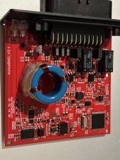
Pretty sure that’s how the rec active 12v BMS works.
 

Attachments

  • E1B4BBBC-841C-4DB2-8FBC-421A15118DF2.jpeg
    E1B4BBBC-841C-4DB2-8FBC-421A15118DF2.jpeg
    181.4 KB · Views: 8
Under certain conditions of imbalance, the ripple current on the cheap 6.3v caps exceeds a level that will cause the capacitor ESR (internal resistance) to cause significant heating of the capacitors which will eventually degrade the electrolytic caps. If you are lucky, they just lose capacitance and become ineffective.

If unlucky they develop high leakage current. If a cap outright shorts out the fuse will blow but a moderate leakage can just drain a cell to zero. BMS is after the balancer so it will do nothing to protect battery, other than give you a warning sign when it shuts down your inverter for low cell voltage.

These caps are directly placed across cells with limited protection against capacitor failure. Do you really want these cheap capacitors putting your expensive cells at risk?

Okay to use this type of balancer for a supervised manually balancing exercise but would not recommend leaving them permanently connected to battery bank unsupervised.
I suspect the cheap capacitor failure is what caused my 8S Hultec capacitor-based balancer to fail in a bad way. By the time I checked it, about half of the capacitors were too hot to touch, and one of my cells had been driven to a way lower voltage than the others. To your point @RCinFLA, I certainly would no longer trust these cheap boards.
 
How exactly would they cause an imbalance amongst the cells? I can see it failing but I fail to see how it can start causing an imbalance. As for the capacitors being cheap or expensive, you could make the same argument on the mosfets used on 99.99% of the Chinese BMS units. Are you going to trust your setup to those too?

How do the Chinese get away with it? The same way they do for so many other items, maybe lower quality, but if you add more and have the component work at 50% rated duty it would work just fine.

Its not different than the many Chinese batteries that are using 2-3 cells in parallel on at 12v batt as this spreads the load across multiple cells.
 
Its not different than the many Chinese batteries that are using 2-3 cells in parallel on at 12v batt as this spreads the load across multiple cells.
I guess one could accuse me of copying the Chinese by having a 3P16S pack. At least I can say I have a BMS made in the USA keeping those cells in line.
:ROFLMAO::ROFLMAO::ROFLMAO:
 
Under certain conditions of imbalance, the ripple current on the cheap 6.3v caps exceeds a level that will cause the capacitor ESR (internal resistance) to cause significant heating of the capacitors which will eventually degrade the electrolytic caps. If you are lucky, they just lose capacitance and become ineffective.

If unlucky they develop high leakage current. If a cap outright shorts out the fuse will blow but a moderate leakage can just drain a cell to zero. BMS is after the balancer so it will do nothing to protect battery, other than give you a warning sign when it shuts down your inverter for low cell voltage.

These caps are directly placed across cells with limited protection against capacitor failure. Do you really want these cheap capacitors putting your expensive cells at risk?

Okay to use this type of balancer for a supervised manually balancing exercise but would not recommend leaving them permanently connected to battery bank unsupervised.

This can literally happen to any component on the BMS and cause the same issue, I suspect most issues people have with this device is due to incorrect installs than it failing.

But going by your logic, any SEU is just as likely to cause the something to happen and its just as likely a BIT flip on the MCU can change the value of a memory table from say 2.5v to .025v

so how are you going to protect your cells from Single Event Upsets? Deploy Military Grade Ionizing Radiation Shielding?

This video explains SEU:

Its quite a common thing.
 
Reviving a bit of an old thread here, but I had a few questions about the use of these little capacitor-based balancers.

1- I see some labeled Heltec (name brand?) and others that are generic with no label but look the same. Any reason to believe the "knockoffs" are any better or worse? I'm thinking they are all likely made with the exact same components but wasn't sure.
2- If properly top-balanced first, then would these be reasonable to add to 48-96ah Headway LFP batteries?
3- Same question as #2 but for RC car Lipo packs and lithium power tool batteries. Mostly lithium ion at 2000-7000mah.
4- Same as #3 but what if the RC or tool batteries were out of balance? How "out of balance" would they have to be to cause a problem?

I have some basic 30A 4s BMS units for LFP, so I'm thinking those would just be better on the Headway batteries. I plan on using them with the "500A upgrade trick" using contactor and fuse. But I don't have enough of the BMS units right now for as many battery banks that I plan on building, thus the other questions about these simple balancers filling that role.

Thanks

My Heltec balancer lasted a week.
 
My Heltec balancer lasted a week.
OK...so why was that? My main ask here is the nature of problems with these things and seemingly most failures are due to very unbalanced cells, but if cells are initially balanced and these are then added I thought maybe they would operate within parameters for which they were meant.
Otherwise, failures could be do to improper use. Or, are these just "overwhelmed" by hooking to high ah batteries? Thus the questions about appropriateness for the RC and tool batteries.
Thanks
 
My Heltec balancer lasted a week.
Both of mine are going on three years continuous service. Maintains excellent balance in all conditions.
My B cells started with no top balance. Took some time to level out but all has been great.

The real benefit to me was that the very tiny balance current of the passive balancing in many BMS is just not enough for 300+ Ah cells.
 
Last edited:
The market is flooded with nasty capacitor balancers, because they are very cheap to manufacture.
They don't work very well, and are potentially unreliable, especially when cheap aluminium electrolytics are used.
The manufacturers of these useless horrors are all in competition with each other, and whoever can produce the cheapest balancer, and makes the biggest claims for it, sells the most balancers. That is what its all about....
That is what the market wants (cheap) and that is what we get.

It does not need to be that way, but something that works a lot better and is potentially more reliable is entirely possible to design and build, but nobody wants to buy something that is expensive, when something dirt cheap is available.

An even bigger problem are the outright deceptions made by the advertising people.
Claims of X amps balancing current are worthless without also defining the voltage difference required to achieve that current.

Its a fact that if you reverse engineer these things, the claims made for them are ridiculous using the capacitor values they actually use in their balancers.

If you have reasonably large cells, and you are serious the only workable system that can transfer enough energy at low enough voltage differentials to be useful, must have a very low impedance between cells, and be able to transfer energy from any cell to any other cell, not just the one immediately next to it. Ultra low impedance is the key.

Now suppose you have one ohm of resistance, and you parallel two cells that have a one volt difference. You might see one miserable amp flowing.
Not five amps, or ten amps. And one volt difference is a hell of a lot !!!
Suppose its only fifty millivolts difference, you might see only 50mA of balance current with one ohm of series resistance in your balancer, and that is a more realistic voltage difference.

If you expect one amp of balance current at 50mV differential (not unrealistic) simple ohms law will tell you that the total resistance needs to be 50 milliohms, or less.
That is not easy to do when you start looking at the combined ohmic resistance of the mosfets, pcb tracks, and the skinny balance wires to each individual cell usually provided.
These balancers always pulse, the balance current is never pure dc. So you also need to take into account the duty cycle as well.
So for a realistic one amp at 50mV voltage differential, the conduction impedance might need to be more like 10 milliohms.

Its entirely possible to build something that can do that, but it would have to be an inductive balancer, not a capacitor balancer, and use a large and relatively expensive single toroidal transformer, heavy windings and heavy wiring to each cell, and very low rds on resistance mosfets, and large beefy pcb tracks. Basically a very large, klunky, and expensive unit to build, that nobody would be prepared to pay for.

And that is how it is.....

End of rant.
 
Active cell balancing with capacitors can be very effective if PWM is used to drive current. In this case, balance current is not dependent on cell voltage differentials.

JK BMS makes a 5A and 10A version of their stand alone Bluetooth, Active cell balancer. It uses super capacitors as a reservoir to discharge high cells then injects into low cells. Works quite well and they are efficient. I have one of each.
You get what you pay for, the 10A version cost $500 a few years ago. IMHO, its worth the price.
 
Why not use even cheaper passive shunt based balancer? Simple and it works.
The problem with that is you cannot both shunt current and make an accurate voltage measurement at the same time.
In fact if you connect a shunt load, disconnect it, and measure the resulting open circuit cell voltage, it can take considerable time for the cell voltage to fully recover.
Another disadvantage is, you are pulling all the good cells down to the voltage of the lowest cell.
It sounds simple, but its actually not simple to get all cells to the same unloaded full voltage, which is what top balancing is.
 
Active cell balancing with capacitors can be very effective if PWM is used to drive current. In this case, balance current is not dependent on cell voltage differentials.

JK BMS makes a 5A and 10A version of their stand alone Bluetooth, Active cell balancer. It uses super capacitors as a reservoir to discharge high cells then injects into low cells. Works quite well and they are efficient. I have one of each.
You get what you pay for, the 10A version cost $500 a few years ago. IMHO, its worth the price.
So some cells are supplying power, while others are receiving power.
Very difficult to make exact precise voltage comparisons while all that is going on.
 
Back
Top