diy solar

diy solar

Hybrid LV 6048 inverter "IN" and "OUT" markings should not be mis-connected. What does this mean?

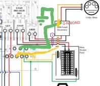
You can follow that drawing with the exception of the grounding. All available main grounds (driven,water, Uffer,gas) and N/G bond should be moved to the disconnect before the Sol-Ark.
Hopefully Sol-Ark will put out a corrected drawing, quickly. I'm sure that it was just an oversight.
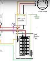
11E183B0-EF3B-4076-9358-D8E9385B1189.jpeg
Like this, Correct? Like you said, the 200A fused disconnect in this case can be considered the main breaker panel, and that is what is supposed to be bonded with neutral, since we don’t want any current running through the neutral wire back to the transformer.

E.g. If 100A ran through ground: Now we would have only 50A to run through the ground wire and we would also allow the other 50A to run through the neutral wire back to the transformer.
 
View attachment 139227
Like this, Correct? Like you said, the 200A fused disconnect in this case can be considered the main breaker panel, and that is what is supposed to be bonded with neutral, since we don’t want any current running through the neutral wire back to the transformer.

E.g. If 100A ran through ground: Now we would have only 50A to run through the ground wire and we would also allow the other 50A to run through the neutral wire back to the transformer.
All circuit conductors (L1,L2, N,G) should follow the same path.
200a disconnect > Sol-Ark > sub panel
 

All circuit conductors (L1,L2, N,G) should follow the same path.
200a disconnect > Sol-Ark > sub panel
I'm sorry if I work mostly in visual illustrations and wiring schematics, I feel things get easily lost in translation with words and sentences. See attached picture:
20230312_103850.jpg

I'm assuming this is what you mean with seperate N-G-L1-L2 paths?

1) Breaker/disconnect for sol-ark with the N-G bond. (First enclosure after transformer)
2) Sol-ark 15K
3) Main breaker panel.

Wouldnt it be important to make sure that the power line transformer isn't connected to the main breaker panel ground? To ensure that it is connected to the first breaker after the meter?
 
I'm assuming this is what you mean with seperate N-G-L1-L2 paths?
Yes
Wouldnt it be important to make sure that the power line transformer isn't connected to the main breaker panel ground? To ensure that it is connected to the first breaker after the meter?
I'm not sure if I understand the question.
The panel in the drawing labeled "main breaker panel", is mislabeled. It's actually a sub panel. (AKA loads panel)
The grids transformer is ahead of your meter.
 
I'm not sure if I understand the question.
The panel in the drawing labeled "main breaker panel", is mislabeled. It's actually a sub panel. (AKA loads panel)
The grids transformer is ahead of your meter.
For the 240VAC transformer output; is the neutral connected to ground?(to a ground rod)?

how would we prevent ground current going through the grid transformer neutral wire if this is the case?

Edit: Is this the only exception to the rule?
Screenshot_20230312-114916_Chrome.jpg
 
Last edited:
Is the 240VAC outout neutral for the transformer on the distribution line connected to ground right at the distribution line (to a ground rod)?
Yes
how would we prevent ground current going through the grid transformer neutral wire if this is the case?
You don't want to prevent it.
Ground current is fault current. For it to open a circuit. (Trip a breaker or blow a fuse) it must return to the source.
 
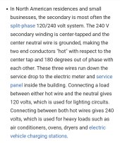
Not sure where you got that paragraph from. But split-phase power is single phase. It's in phase, not 180deg out of phase. You couldn't get 240v if it weren't in phase.
 
Center tap single phase is mathematically equivalent to two phase with 180 degree offset plus a neutral. The latter is after all how 120v inverters are stacked to give 120/240. No center tap transformer in sight in half the designs.

But this is a red herring wrt how to do the N-G bond correctly
 
Center tap single phase is mathematically equivalent to two phase with 180 degree offset plus a neutral. The latter is after all how 120v inverters are stacked to give 120/240. No center tap transformer in sight in half the designs.

But this is a red herring wrt how to do the N-G bond correctly
Incorrect.
But, if you don't get it. You probably never will.
 
Incorrect.
But, if you don't get it. You probably never will.

How would connecting load across the L output of two in-phase, synchronized 120V stacked inverters generate 240V? The two outputs would both be at the same voltage if they are in-phase, so 0V.

I agree that you should NOT call the utility power two 180 degree phases because there is a single phase going to the utility transformer.

But there are multiple ways to generate proper AC power for 120/240 appliances if you're not connected to the grid.
 
Incorrect.
But, if you don't get it. You probably never will.
B84AF8C4-BC3F-4D33-8978-678F39B40E33.jpeg

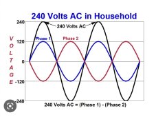
Each phase does look 180degrees apart.

But together they indeed do look like they are adding one another instead of subtracting.

I assume this is why you read 0A on the neutral with a multimeter?

And the reason we read 240VAC between L1 and L2 is because when one is 120VAC, the other is -120VAC and the distance between the two are 240VAC. Since to a multimeter doesn’t know what 0 is, it only knows the oscillation…
 
I assume this is why you read 0A on the neutral with a multimeter?

You read 0A on neutral if the 120V loads are completely balanced or all loads are 240V.

IMO it's more correct to call the two conductors legs rather than phases in 120/240. Because most of the time they are not from different phases of a power source.
 
When two inverters are placed in series they produce 240v. The center tap between them gives you 120v.
When two inverters are placed in parallel you only get 120v.
Series = double the voltage, and amperage remains the same.
Parallel = double the amperage, and the voltage remains the same.
 
When two inverters are placed in series they produce 240v. The center tap between them gives you 120v.
I was considering the type of stacked inverter where you connect Neutral to Neutral (L1 N1 - N2 L2). In that case wouldn't they need to have opposite phase to generate 240V?

I checked on page 14 of the 6500EX manual, this inverter is connected N-N for split phase.

I agree if you connect N1 L1-N2 L2, then the AC should be in phase. However this feels weird to me because this means the potential between "N" and EGC will be much higher than in 120V operation. Also it's counterintuitive for terminals labeled "N" on the inverter to not be grounded conductors. Feels like something UL will be pissed about.
 
OK, those videos were helpful. Thanks for sharing. From the perspective of manipulating AC from transformers, the in-phase explanation is the right way to go.

However, I think the 180 degree out of phase is sometimes the correct way of talking about inverter stacking. It depends on how the manufacturer specifies the wiring for the inverters.
 
However, I think the 180 degree out of phase is sometimes the correct way of talking about inverter stacking. It depends on how the manufacturer specifies the wiring for the inverters.
Agree: When a Single AIO produces L1,L2,N with one unit, and multiple units are described as parallel by the manual only to increase output capacity (Voltronics example MPP6048)
Vs Creating the split phase using at least two AIO units and adjusting the settings such that the two units (or more) together create 120-N-120 (Voltronics example MPP 6548) in the settings the user can select for example 120-degree angle for 208V 3P or 180-degree angle for 120-240.
 
I was considering the type of stacked inverter where you connect Neutral to Neutral (L1 N1 - N2 L2). In that case wouldn't they need to have opposite phase to generate 240V?
Current doesn't flow unless it's in phase.
When two inverters are placed in series to create twice the voltage. They must be kept in phase to flow current. But the timing of the switching Fets (creating AC current) are 180deg from each other. So that the voltage is additive. But the end result is still one in-phase sinewave.
 
Back
Top