diy solar

diy solar

Hybrid LV 6048 inverter "IN" and "OUT" markings should not be mis-connected. What does this mean?

LasseH

New Member
Joined
Mar 10, 2023
Messages
24
Location
United States
Hello and thanks for checking out my post.

I've never designed a solar system before, so hopefully none is gonna crush me in my newbie questions regarding the implementation.

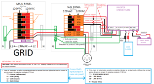
I've been looking for examples of wiring, but most of the drawings online does not show the specific wiring schematic of inverters and how it is connected to the main breaker panel and the sub panel. There's a lot of video's of people showing off their finished wiring projects, but little to no images of their wiring schematic. So... I decided that I would give it a go. (please see image below for illustration)...

I decided to go with the MPP hybrid LV6048 using split phase connection. This is where I came across a lot of confusion.

I was wondering if this wiring looks ok? I fail to understand what the difference between input and output terminals are on this grid-tied/off-grid hybrid inverter, and I was hoping that some of you would be able to let me know if I'm on the right track?

1) Part of my concern relates to the fact that it states that "IN" and "OUT" markings should not be mis-connected. What does this mean?
2) Should both input and output be wired up with L1, L2, N and G?
3) Should they both have a 40A pole breaker?

Thanks!
Offgrid.png
 
Last edited:
How do you plan on disabling the grid? I'm not familiar with lv6048 but the way you have it wired you will fry it by sending voltage/current through the exit hole (pun intended) She doesn't like that!
 
@Zapper77 That was my confusion exactly. There would be no point in having input and output terminals if it was able to switch between getting and giving at the same time.

My main questions I guess would be if both of them are even necessary...? Can I do with one without the other? (Input or output terminal only? My understanding is that the inverter is being powered by the battery anyways, so why even have AC input?)

I have this idea that the two sets of terminals is to provide a different path of where it is getting voltage to charge up the batteries from the grid, while having a exit hole (as you put it), back to the house as well.

Charge battery to full capacity using grid while also providing solar power straight to the house?

Or would the AC power from the inverter from the solar just end up going straight back into the inverter, causing a infeed/discharge paradox?
 
Grid to inverter, inverter to a independent "critical load" subpanel that has no direct grid connection. The critical load panel in only powered when the inverter is on or in grid bypass.
 
One warning, it's the middle of the night and I woke up to get a drink of water. I got sucked into my phone notifications. So anything I type may need edited in the morning. ?
 
@Zapper77 Feels weird to shut off the grid? Bypass it I mean? Is that necessary?
1) Is there no way to use inverter to feed all loads of the house together with the grid?
2) Charge batteries with solar and primarily use the power from inverter over the grid whenever possible.
3) Not backfeed the grid. Zero power back to the utility company.

Is this even possible? Or do I need a completely different inverter in order to pull this off?
 
Where the hell did this drawing come from?
That's all kinds of wrong.
 
@Zapper77 Feels weird to shut off the grid? Bypass it I mean? Is that necessary?
1) Is there no way to use inverter to feed all loads of the house together with the grid?
2) Charge batteries with solar and primarily use the power from inverter over the grid whenever possible.
3) Not backfeed the grid. Zero power back to the utility company.

Is this even possible? Or do I need a completely different inverter in order to pull this off?
Something like this?
 
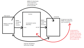
I made another drawing to illustrate what I am fearing.

It's possible that this is also wrong, so please do let me know if this is the correct way of looking at it..?

Edit: in the red arrow I meant to say in parallel, not in series…

1678447066256.png
 
Last edited:
1. This is an off grid AIO. (All In One)
2. Not a grid-tied unit. (However, it can accept a grid input)
3. This type of unit is designed to be placed between the grid and the loads.
 
This inverter can be used completely off grid. Which would mean you’d be installing a panel and beakers for your loads. Or it can be used in a hybrid fashion. You can install a sub panel and the inverters feed those loads with the grid flowing through the inverters in the event the batteries are low. Either way, you need a separate panel.

There are some inverters that can push power back into the main panel with CT’s monitoring the energy use. But that’s a whole different story. And yours doesn’t have that capability.
 
Hello and thanks for checking out my post.

I've never designed a solar system before, so hopefully none is gonna crush me in my newbie questions regarding the implementation.

Before you wire anything, you need to research. Upper right corner of your screen, there is a search button. You will need to decide how N-G bonding will be accomplished first and foremost.

I've been looking for examples of wiring, but most of the drawings online does not show the specific wiring schematic of inverters and how it is connected to the main breaker panel and the sub panel. There's a lot of video's of people showing off their finished wiring projects, but little to no images of their wiring schematic. So... I decided that I would give it a go. (please see image below for illustration)...

I decided to go with the MPP hybrid LV6048 using split phase connection. This is where I came across a lot of confusion.

I was wondering if this wiring looks ok?

Absolutely not ok. Start with this thread and the discussion on N-G bonding for this particular inverter. https://diysolarforum.com/threads/lv6048-output-neutral-ground-bonding.33719/
 
@Gavin Stone 1) Can you recommend any inverters that have a CT monitoring system? I may have to rethink my whole strategy.
2) Also, do you know of any inverters like this that is also capable of not shutting off when the grid is down?
 
The EG48kw/megarevo can do that. The Solark is really designed for that situation. You can run your grid through the unit and treat it as a backup. But pretty much all the these units will need a sub panel also.
 
@Gavin Stone 1) Can you recommend any inverters that have a CT monitoring system? I may have to rethink my whole strategy.
2) Also, do you know of any inverters like this that is also capable of not shutting off when the grid is down?
What's your ultimate goal in using the solar system? Just as a backup in case the grid goes down or to get you using less grid power?
 
The EG48kw/megarevo can do that. The Solark is really designed for that situation. You can run your grid through the unit and treat it as a backup. But pretty much all the these units will need a sub panel also.
the 15K solark seem to be possible to run a input of 200A, right? So if you have a house with the size main breaker panel at 200A, you’d be ultimately able to leave the entire main breaker empty connect the L1, L2, N and G straight to the Sol-ark and have the entire house to supplied by the Sol-ark instead of the grid. And whenever the battery gets too low, it can simply draw a bit of Current from the Grid? Sounds awesome.

If everyone had a 15K sol-ark.. All you’d need is pretty much pay for solar panels. ? And not worry about which loads in your house to seperate into a separate sub panel…

That would sound like an ideal world to me. Power to the people. But keep grid tied just in case of clouds etc. ☁️
 
Last edited:
Back
Top