diy solar

diy solar

I’d like to understand how this is ok

Bluedog225

Texas
Joined
Nov 18, 2019
Messages
2,931
This is a photo of my Victron lynx distribution bar. The is the negative bus bar.

The stud with the red ring terminal around it is not fused. It is for grounding the system.

Given this thing is rated for a lot of amps, how can landing a ground wire [edit] lug on top of that tiny little ring terminal be OK?

It seems to deny good contact with the substantial negative busbar. The Victron manual is very clear that that red ring terminal is supposed to be where it is and you are not to remove it. And there is not enough wire to lift it out of the way.

I could use a fork terminal connector to slide under the red bus bar, but the manual gives no indication that this is the right way to proceed.

I don’t doubt Victron is doing this correctly, I just don’t understand how this can be appropriate.

Any ideas?
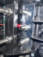


IMG_8906.jpeg
 
Last edited:
Seems pretty poor to me, I was trying to work out what is was at first given I've only used modified Lynx Power Ins. I'm surprised there's not enough wire to remove it, would a slight disassemble of the unit allow the ring terminal to be released? Possibly removing the screws that hold the plastic part where the main fuses connect? I'm no expert but that small Philips screw that holds the busbar down seems like it would have been a much more appropriate mounting point for such a low current connector..

Come to think of it.. I've never grounded my negative, I didn't really think it was necessary. I ground my Multi chassis and MPPT chassis, guess I'll have to look into grounding the battery negative too.
 
Last edited:
Maybe Dexter knows.

@HighTechLab

I think I could disassemble the unit and free it. Maybe. But not eager to mess with a brand new deal.

Note-the red wire to the left is a different lead.
 
I'm no expert but that small Philips screw that holds the busbar down seems like it would have been a much more appropriate mounting point for such a low current connector.
me too ^^^

The stud with the red ring terminal around it is not fused. It is for grounding the system.
Red? o_O Did Victron run out of green or green-yellow insulation?
 
This is a photo of my Victron lynx distribution bar. The is the negative bus bar.

The stud with the red ring terminal around it is not fused. It is for grounding the system.

Given this thing is rated for a lot of amps, how can landing a ground wire [edit] lug on top of that tiny little ring terminal be OK?

It seems to deny good contact with the substantial negative busbar. The Victron manual is very clear that that red ring terminal is supposed to bev where it is and you are not to remove it. And there is not enough wire to lift it out of the way.

I could use a fork terminal connector to slide under the red bus bar, but the manual gives no indication. That’s the right way to proceed.

I don’t doubt Victron is doing this correctly, I just don’t understand how this can be appropriate.

Any ideas?


View attachment 183525

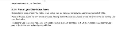
That's not what the instructions say.

Screenshot_20231217_125607_Drive.jpg
 
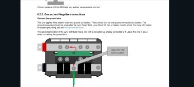
That is referring to the cable connecting to the positive side which is easily removable, the one blue is pointing out is on the negative bar and the instructions state to place the lug over top of it.
K

Isn't that for the EGC if you're bonding battery negative?

Not to carry current.

In other words that is not where you connect battery negative.
 
K

Isn't that for the EGC if you're bonding battery negative?

Not to carry current.

In other words that is not where you connect battery negative.
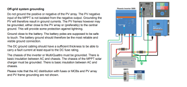
Yes but... "The DC ground cabling should have a sufficient thickness to be able to carry a fault current at least equal to the DC fuse rating"
Still don't like a poor connection :confused:
 
This is a photo of my Victron lynx distribution bar. The is the negative bus bar.

The stud with the red ring terminal around it is not fused. It is for grounding the system.

Given this thing is rated for a lot of amps, how can landing a ground wire [edit] lug on top of that tiny little ring terminal be OK?

It seems to deny good contact with the substantial negative busbar. The Victron manual is very clear that that red ring terminal is supposed to bev where it is and you are not to remove it. And there is not enough wire to lift it out of the way.

I could use a fork terminal connector to slide under the red bus bar, but the manual gives no indication. That’s the right way to proceed.

I don’t doubt Victron is doing this correctly, I just don’t understand how this can be appropriate.

Any ideas?


View attachment 183525

You're not supposed to mount a current carrying conductor there.

That is why there is no positive post above it.

They intend for it to be mounting post only if you're grounding/bonding battery negative.
 
Yes but... "The DC ground cabling should have a sufficient thickness to be able to carry a fault current at least equal to the DC fuse rating"
Still don't like a poor connection :confused:

It's for bonding battery negative to a grounding electrode (earth), not for protecting DC faults.

Notice the green color of the wire in the diagram.
 
It's for bonding battery negative to a grounding electrode (earth), not for protecting DC faults.

Notice the green color of the wire in the diagram.
Just quoting what Victron says.. If they feel the cable should be sized for the DC fuse, then I reckon the connection should be better too, albeit I understand there's not going to be any current passed in normal operation. Well I'm not sure in what situation it would ever pass current.. but it says what it says o.o
 
Just quoting what Victron says.. If they feel the cable should be sized for the DC fuse, then I reckon the connection should be better too, albeit I understand there's not going to be any current passed in normal operation. Well I'm not sure in what situation it would ever pass current.. but it says what it says o.o

They aren't referencing fault-carrying (lightning, a/c short to DC negative etc) conductors in that statement. They are referencing using the proper size fuses for the wire gauge being used on the given circuit.
 
Maybe I interoperate what they say a little differently, not that I should think about it too much though, I don't even have a DC ground cable ?
Capture.PNG
 
Back
Top