diy solar

diy solar

I have a plan!

DanielWNC

New Member
Joined
Aug 6, 2023
Messages
4
Location
Asheville, NC
Hi everyone!

I need a mid size 500watt or so solar power in the short term, but I want to have the ability to scale up. So my plan is to overbuy some components, and leave the rest of the system viable for increasing substantially.

Having never done this before, I have spent a fair amount of time putting a plan together, and I would like you to review what I came up with as the eventual setup. I don't know if the components are "right-sized" to match each other, or if the (especially) wiring guages are correct, and a few other questions are on the plan itself.

If this is not the correct forum for this, please point me in the right direction.

Thanks in advance, I am so glad I found this discussion board!
Dan
 

Attachments

  • solar power system design.odw.pdf
    35.8 KB · Views: 16
LInk #1 in my signature.

Design the final system and see how you can piecemeal it.

1. 1.25X the wire rating.
2. Select wire based on 1) ampacity rating and 2) voltage drop
3. 40A * 13.8V (typical LFP charge current) = 552W. With 4 panels in parallel, Voc should be fine. If you place them 4S or add more panels in series, you may exceed the MPPT voltage rating. Additional panels will need more MPPT or a higher current MPPT. 40A is the OUTPUT, not the input.
4. 18awg PV wire. 4P panels are going to yield about 20A - way above rated for 18awg. 40A out from the inverter is even worse. 6awg inverter wire from battery to bus bars. Your future 4000W inverter, which is absurdly high for 12V, can pull 367A at 12.8V. This should encourage the insulation of your 6awg wire to catch fire.
5. Not an expert.
6. Yes.
6b. a charger capable of charging to 14.0-14.4V and floating at 13.5V.
 
Rev 2

I appreciate the previous response, but I don't have the familiarity and experience to readily apply the formulas and calculations, because I've never done them before. I came up with the values I have by doing *exactly* that, and applying those formulas, but there is very confusing and conflicting information out there. I think an experienced and familier person may be underestimating how difficult and confusing it can be for a first time try starting from zero understanding.

So now I've spent 4 days on this and my new chart is the absolute best I can do, based on all the formulas and information I can find, calculators, charts, articles, the response above, 2 pots of coffee, and 4x222mg Naproxen Sodium.

I just need the correct values, if anyone can help, I really appreciate it. With the correct values in place, I can reverse engineer it, and see where I am doing calculations etc incorrectly. From there I can probably make changes as necessary on my own, but without it, theres no way for me to figure out what I'm doing wrong.

Again please keep in mind this is my first time out, starting out with zero knowledge or experience here.
 

Attachments

  • dans big idea rev 2.pdf
    35 KB · Views: 9
Overall the diagram is improved.

Amps = power/voltage / 85% (efficiency)

500W/12V/.85 = 49A - your wire must support this. Your fuse/breaker should be 1.25X this.
2000W/12V/.85 = 196A - your wire must support this. Your fuse/breaker should be 1.25X this.

Standard 8awg and 2awg, respectively, won't handle those currents. If you've selected a wire that supports those currents, that's fine.

Additionally, the 2awg wire between shunt and bus must support both inverters, so it should be rated for 245A

The 8awg to the 40A MPPT is adequate. 40A * 1.25A = 50A breaker.

The other consideration is if the voltage drop is acceptable per the linked calculator.

Lastly, since you have 4 panels in parallel (4P), each panel must be fused or have a breaker. The easiest method is to simply install a MC4 inline fuse. Additionally, MC4 connectors are typically only rated for 30A. 4P will be fine, but 6P may be too much. Verify with the panel Isc rating. You can mitigate high current by configuring both series and parallel, e.g., 2S2P for the initial 4 panel configuration would require no fusing. Adding two additional panels to form 2S3P would require a fuse on each string of 2S panels; however, a 3S2P configuration would not require fusing. 2S3P or 3S2P will not exceed MC4 30A rating.
As I said earlier, I have no clue. I don't know what guage wire I need for 49A or 196A. I have come up with a different gauge 4 or 5 times. Same for all the other points. 6ga & 2/0?

Sorry but I am *extremely* exasperated with this. I just need a few specific numbers and I can't get them or figure out what they are, or figure out why I can't figure out, or figure out why I can't get the specific information, or figure out why it is so hard to get a few specific numbers: what guage do i need for each wire? I tried to explain repeatedly that I just needed the simple answer.

Far too frustrated now. I will pay an electrician to write it in for me. Thanks for the help anyway.
 
I was about to post the Bluesea chart, BobR beat me to it.

Not to add to the confusion but wire gauging is more complicated than most people expect so don't feel too bad. The Bluesea chart will get you along just fine and you shouldn't have to worry about insulation ratings if you use it because different flavors of the insulation also change the sizing. Catching the fact that there is a HUGE difference between 2AWG and 2/0 AWG can be a real killer.

In short, reference the Bluesea chart and when it doubt, go up one size.
500W/12V/.85 = 49A - your wire must support this. Your fuse/breaker should be 1.25X this.
2000W/12V/.85 = 196A - your wire must support this. Your fuse/breaker should be 1.25X this.
So for perspective and maths help:

49a wire doesn't exist, so the chart says 6AWG for a run less than 10ft round trip (that's total wire length from the battery to the inverter back to the battery). For the fuse it's 49a * 1.25% = 61.25a breaker. Again, that doesn't exist so you could use a 60a and be fine or a 65a if you can find it.

196a wire is also an odd number, so round that up to 200a and check the chart to see 2/0 AWG wire for that same 10ft round trip run and the breaker will be 196a * 1.25% = 245a, so throw a 250a breaker/fuse on that one.

This is one of those situations where the math doesn't have to be perfect because nobody makes a 31.783a breaker, so you just gotta get close. Yes, your calculations for 6AWG and 2/0awg look correct. (y) It looks like the diagram is good other than needing 2/0 instead of 2 so just fix the text.

Just as a though, is there a reason you're doing parallel instead of series connection? If you ran those panels in series as a single string you wouldn't need splitters, combiner boxes, etc.

Lastly, since you have 4 panels in parallel (4P), each panel must be fused or have a breaker. The easiest method is to simply install a MC4 inline fuse.
If you're running that many panels/strings in parallel, seriously look at a Combiner Box which will do your fuses, lightning protection, and main disconnect all in one place. Much more reliable than inline fuses and splitters.

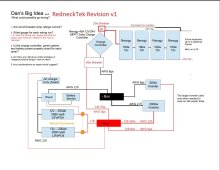
Here's what I came up with for optimizing your drawing and adding in a couple breakers for disconnects and protection:

Dan's Idea Rednecktek Revision.jpg
 
Last edited:
Two points,
1, Keeping in mind you want to be able to expand,You haven't noted the system voltage that I see but I wouldn't recommend a 12 volt system. Once you buy your inverters you're stuck with their voltage unless you want to buy new ones down the road.
Start with 24 volts or even 48, which would require 2 more batteries.
2, 100 watt, 12 volt panels are much more expensive, per watt than the larger format panels. You can find great pricing at Santan Solar and Solar Steals for new and used panels.
 
If I understand you, then my diagram is fine except for all 2ga needs to be 2/0?

- 10ga PVI > controller, up to 6 panels parallel
- 8ga and 60amp breaker from > controller > bus > 500w inv
- 2/0 and 250amp breaker from > battery > bus > 2000w inv

Other than wire and fuse routing, if I change the PV to series does that improve efficiency in some way?
 
If I understand you, then my diagram is fine except for all 2ga needs to be 2/0?

- 10ga PVI > controller, up to 6 panels parallel
6 panels in parallel is a LOT of amperage, like 30+ amps, gonna need 8AWG at least. Going in series would be better unless you've got shading issues.
- 8ga and 60amp breaker from > controller > bus > 500w inv
A 50a breaker from the controller would be better sized. 60a to the little inverter is good.
- 2/0 and 250amp breaker from > battery > bus > 2000w inv
(y) (y)
Other than wire and fuse routing, if I change the PV to series does that improve efficiency in some way?
The length of the wire and thickness are affected. If you take your bog standard Generik 100w panels that put out 5a @ 20v, then 6 in parallel is 30a (maxxes out the 10AWG capability at that length) and requires 6 fuses and lots of splitters or a hefty combiner box (not cheap). At 25ft each way (which never actually meets that because of extra length up here and a loop there and so on) you need to look at the Bluesea chart to see your voltage drop is going to be enough of a hit you'll have a really hard time reaching charging voltages because each panel would have to get to charging voltage (usually battery +5v minimum). If you're running 10AWG and taking a 10%+ voltage drop from that, now the panels need to get to Battery + 5v + 10% to even get started doing anything.

Going in series however with those same 6 panels gets you 120v @ 5a which is well within the capabilities of 10AWG wire over that length of run taking less than a 3% hit, AND removes the need for all the points of failure between the fuses and splitters. You can take that wire directly to the charge controller and call it a day. It also requires less light to reach solar charging voltages because each panel only has to come up with 1/6 of the required voltage meaning you're harvesting power in lower light conditions like clouds, rain, early morning and late afternoon sun. You'll basically get to add a bit of working time to generate.

Does that make sense? That's why I changed the diagram.
 
Well if you're using 100w panels, they average a little over 20v so a 150v SCC would let you have 6 panels in series. You can always do another 6s string in parallel with that before you need to start worrying about fuses and such.
 
Back
Top