diy solar

diy solar

Idea to safely charge inverter capacitors

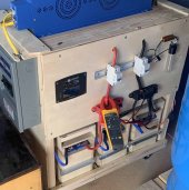
This reply is to the original post which was just an idea at the time. I did execute the plan and the idea worked. The BMS did not see a dead short and the inline resistor charged the capacitors. The visual of the light turning on (lamp in line with the resistor) and then off gave me the indication that the capacitors have been charged and I can switch on the circuit breaker. The process is as follows:

1) close the positive breaker while the negative breaker remains open
2) switch the pre-charge parallel circuit on (close the switch). The lamp turns on briefly - about a second and then dims.
3) close the negative breaker.
 

Attachments

  • IMG_5402 2.jpg
    IMG_5402 2.jpg
    279.5 KB · Views: 20
I find my Overkill BMS when off will leak enough current to slowly recharge or maintain charge on the inverter input.
 
Since you have 6x eg4 batteries the problem is divided by 6.
I suggest you turn on all the batteries before you turn on the inverters.
Also the eg4 batteries have a priming circuit if I'm not mistaken.
Wouldn't the problem be 6x worse?
With 6 parallel batteries, you'll have 1/6th the IR to allow even higher in rush current.

But, if those do have a precharge circuit, wouldn't you turn on the breakers on the batteries last?
 
@400bird Maybe. The inverter will be fractionally limited by the wires from the bus to the inverter. With enough parallel packs that might be just enough to keep them below the threshold. Also, while an empty capacitor may be close to an infinite current sink, it isn't quite. Of course, that relies on the batteries being on and then the switch to the inverter being closed. If the switches are on the batteries, then each will see a short in very rapid succession and cut off again.

Yes, the precharge is generally across the battery switch, which would be turned on last. Technically a/the precharge can be across any switch that might have large empty capacitors. In a multi-inverter setup, putting prechargers across the inverter switches may even be more practical anyway. In practice, however, if one inverter is running and the switch of another is closed, the new one will draw in part from the running inverter's capacitors, reducing the demand on the battery. Exactly where the boundaries are would have to be determined on a system by system basis.
 
Wouldn't the problem be 6x worse?
With 6 parallel batteries, you'll have 1/6th the IR to allow even higher in rush current.
I see your point.
I failed to appreciate just how much a capacitor can look like a dead short.

I think the component most susceptible to damage from in-rush current in this case is the BMS.
If the all_in_one is damaged by its own in-rush I think that is a warranty problem.
If the battery BMS or manual reset breaker is damaged by in-rush current I think that is also a warranty problem.
If the fuse on the branch circuit pops I think that is an architecture problem.
Would be wise to check the product manuals to be sure there are no limitations on the usage model.
But, if those do have a precharge circuit, wouldn't you turn on the breakers on the batteries last?
Not sure how the primer circuit is activated.
Also some inverters pre-charge when their switches are turned on and some don't.
 
Last edited:
I see your point.
I failed to appreciate just how much a capacitor can look like a dead short.

I think the component most susceptible to damage from in-rush current in this case is the BMS.
If the all_in_one is damaged by its own in-rush I think that is a warranty problem.
If the battery BMS or manual reset breaker is damaged by in-rush current I think that is also a warranty problem.
If the fuse on the branch circuit pops I think that is an architecture problem.
Would be wise to check the product manuals to be sure there are no limitations on the usage model.

Not sure how the primer circuit is activated.
Also some inverters pre-charge when their switches are turned on and some don't.
Yes exactly. The BMS FETs will fry before anything else does. It's actually quite common and the number one reason that distributors have to deal with warranty claims on lifepo4 packs. I've seen a pile of BMS that were fried from inrush. The first version of Battleborn BMS had this problem many years ago. Since then, manufacturers have beefed up the BMS or added pre charge circuits.

If you're going to have a precharge circuit, they should add it to the battery. Because as you said, if the inverter cannot handle it, that should be a warranty issue for the inverter, not the battery.
 
I totally agree, you also run the chance of impacting the component you close (the arc isn't good for breaker)
That is why I wanted the breakers closed before the current flows.
Hopefully the all_in_ones don't charge the caps until the on/off switch is set to on.
 
I built this for my small 48V system after having my Growatt disconnected for a couple of hours and forgot the precharge. Still can't find my cat ?
 
I'm planning an automatic pre-charge for my 1500w inverter (for a DIY solar generator):
Parts:
- 12v time delay relay
- 12v Lifepo4 battery
- 12v 1500w inverter
- Anderson connectors
- 5-10w Ceramic resistor
- DC circuit breaker (MCB)
- Wiring

Basically, the inverter and battery will be disconnected until I need to use them.
When I connect the Anderson plug from battery to inverter, the 12v relay will also be powered. When the relay is powered, it will connect the input and output side of the DC MCB using the resistor, for a pre-defined time (say 5-10 seconds).
During this time a built-in LED lights up in the relay stating that it's connected. When the light turns off (relay delay time has passed, and relay opens) then I know that the inverter is pre-charged and I can turn on the MCB.

Does this help you?
any chance you can share a diagram of this solution - even if hand drawn? Just want to make sure I get it right. Thx
 
Sure:
IMG_20220324_230630_339.png

The idea is to use a relay that connects the two sides of the DC breaker (when the breaker is off), through a resistor. The relay stays on for a set period of time, and then disconnects (untill next time it's power is disconnected and then connected again).
Then you can turn on the DC breaker.

This is the relay I got:
 
Last edited:
Bear in mind that you only have to pre-charge the circuit once when you hook up the inverter. Unless your battery goes to zero or if you disconnect is the only reason to have to pre-charge it again.
 
Bear in mind that you only have to pre-charge the circuit once when you hook up the inverter. Unless your battery goes to zero or if you disconnect is the only reason to have to pre-charge it again.
That has not been my experience with several Growatts, and a handful of 48 volt inverters. Few hours or less disconnected lets the genie out.
 
That has not been my experience with several Growatts, and a handful of 48 volt inverters. Few hours or less disconnected lets the genie out.
I assumed @GLC was assuming there would be no disconnection, as did I.
Is there any reason an inverter should not be precharged anytime it has been disconnected from the batteries? We don't want the Jeannie getting away when we're not looking, right?
 
I assumed @GLC was assuming there would be no disconnection, as did I.
Is there any reason an inverter should not be precharged anytime it has been disconnected from the batteries? We don't want the Jeannie getting away when we're not looking, right?
From what I have learned and what Will has shared, a small inverter like 1000 to 1500 watts may not need to be pre-charged but it is always a safe thing to do. But, "Always" pre-charge a larger inverter. And yes, pre-charge every time you disconnect the batteries. I have moved batteries around where I took less than five minutes and still got a spark. Rule of thumb, always pre-charge just in case when batteries have been disconnected.
And I did state this in my previous post-"Unless your battery goes to zero or if you disconnect is the only reason to have to pre-charge it again."
 
I don't understand the need for the time delay, isn't a permanent bypass with a switch in series with the resistor (to switch off the circuit during maintenance) easier?
 
I don't understand the need for the time delay
The time delay is to give the precharge circuit time to charge the capacitors before turning on the main switch. That way the spark is avoided on the main switch.
The main switch would work fine for maintenance.
 
Thanks, I had understood but after switching on the main circuit, by the relay or the switch, there is almost no current going through the precharge circuit! By leaving it in service, wouldn't we protect the main contacts from the induction choke effect of an untimely cut-off?
Two birds with one stone.
 
Sure:
View attachment 88516

The idea is to use a relay that connects the two sides of the DC breaker (when the breaker is off), through a resistor. The relay stays on for a set period of time, and then disconnects (untill next time it's power is disconnected and then connected again).
Then you can turn on the DC breaker.

This is the relay I got:
I just completed my pre-charge circuit, with the time delay relay.
It looks like this (underneath the relay is a 12v fan control, just ignore it for now):

20220504_113828.jpg20220504_113821.jpg20220505_210712.jpg

After some quick testing, it seems to work great. The relay goes on for about 10s (adjustable), enough time to turn in the main switch, when connecting the battery to the inverter. After those 10 seconds, the relay opens. It will do the time delay again, only if the battery is disconnected and connected again.

My setup is for a portable solar generator, where the battery will have its own disconnect switch too, so I needed a pre-charge circuit, to limit the inrush.
 
Back
Top