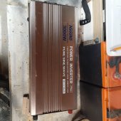
Are Inverters repairable? I bought a used 3k psw inverter and it shat the bed after about 6 months of use. It just Beeps and flashes. There are No instructions for troubleshooting and cannot find the brand name on line although looks like it was never used and decent quality. I checked the fuses and looked for burn marks but all looks good. Any ideas what to look for?


You are using an out of date browser. It may not display this or other websites correctly.
You should upgrade or use an alternative browser.
You should upgrade or use an alternative browser.
Inverter repairable?
- Thread starter sparkyv
- Start date
MisterSandals
Participation Medalist
Happen to have an IR camera to look at the innards (safely!) with it powered on?Any ideas what to look for?
MisterSandals
Participation Medalist
Here is a similar journey (successful).I do have a infared camera.

Magnum MS4448PAE charger quit working.
Don't have pict of board but is located in AC input section near connect relay. It is connected between AC input and connect relays so it can read AC input voltage and phase to provide info for inverter controller to synchronize to AC input before it closes connect relay putting inverter in...
 diysolarforum.com
Bud Martin
Solar Wizard
- Joined
- Aug 27, 2020
- Messages
- 4,844
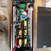
Can you open it up and show good clear pictures of the inside?
there seems to be excessive amount of white stuff on the transformer windings. ??Can you open it up and show good clear pictures of the inside?
Attachments


MisterSandals
Participation Medalist
You need to hear from someone like @RCinFLA, hopefully this will summon his spirit...there seems to be excessive amount of white stuff on the transformer windings. ??
RCinFLA
Solar Wizard
- Joined
- Jun 21, 2020
- Messages
- 3,565
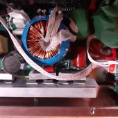
Looks like you have seagull problems.
It looks like the sinewave PWM filter inductor. They goop it up to suppress the buzzing noise it makes. Not the issue. There will also be about a 2 uF foil capacitor across AC output. The L-C filters the AC output PWM from IGBT's in H-bridge output stage.
Battery -> MOSFET's -> ferrite transformer-> rectifiers -> black electrolytic HV DC caps (about 250vdc for 120vac inverter) -> PWM sinewave generation IGBT (4) H-bridge -> output PWM L-C filter. -> AC output. That is the basic functional path.
Looks like a regular run of the mill sinewave inverter. The five transformers are battery to HV DC boost converter. Each transformer usually has its own set of MOSFET primary side drivers. Basically, just parallel group of smaller transformers to build higher power output. Output boost up battery voltage to HV DC. It runs about 18-24 kHz. HV DC PWM chopped by IGBT's and filtered to sinewave by L-C filter.
Common for some of the battery side MOSFET's to be toast. Check drain to source of each for being shorted. There is likely rectifier diodes on secondary side of five transformers along with transformer primary side MOSFET's mounted on the heat sinks on each side. Check diodes also. Last common problem is blown IGBT's for sinewave PWM. The IGBT's may also be mounted on heat sink on the side or separate heat sink in middle of board. The IGBT's will have connections to the gooped toroid inductor.
There are a lot of other smaller support functions like power device drivers but that is particular to a given model design.
You might search some Youtube video repairs on regular inverters. You might get lucky.
Last edited:
Nobodybusiness
Collecting the leftovers of the Great Sky Reactor.
I’m not sure most people are setup for component level repair.Looks like you have seagull problems.
It looks like the sinewave PWM filter inductor. They goop it up to suppress the buzzing noise it makes. Not the issue. There will also be about a 2 uF foil capacitor across AC output. The L-C filters the AC output PWM from IGBT's in H-bridge output stage.
Battery -> MOSFET's -> ferrite transformer-> rectifiers -> black electrolytic HV DC caps (about 250vdc for 120vac inverter) -> PWM sinewave generation IGBT (4) H-bridge -> output PWM L-C filter. -> AC output. That is the basic functional path.
Looks like a regular run of the mill sinewave inverter. The five transformers are battery to HV DC boost converter. Each transformer usually has its own set of MOSFET primary side drivers. Basically, just parallel group of smaller transformers to build higher power output. Output boost up battery voltage to HV DC. It runs about 18-24 kHz. HV DC PWM chopped by IGBT's and filtered to sinewave by L-C filter.
Common for some of the battery side MOSFET's to be toast. Check drain to source of each for being shorted. There is likely rectifier diodes on secondary side of five transformers along with transformer primary side MOSFET's mounted on the heat sinks on each side. Check diodes also. Last common problem is blown IGBT's for sinewave PWM. The IGBT's may also be mounted on heat sink on the side or separate heat sink in middle of board. The IGBT's will have connections to the gooped toroid inductor.
There are a lot of other smaller support functions like power device drivers but that is particular to a given model design.
You might search some Youtube video repairs on regular inverters. You might get lucky.
I understood what you are saying and can recognize the layout because of Military training.
Most wouldn’t know how to ohm a resistor much less check gate voltages or a short between Gate and collector.
It would be great if people did have that kind of knowledge but that is not something you pick up on the fly..
I think when most people say “can this be fixed” it’s more of a “can I swap out a board”.

Hedges
I See Electromagnetic Fields!
- Joined
- Mar 28, 2020
- Messages
- 20,916
I’m not sure most people are setup for component level repair.
...
I think when most people say “can this be fixed” it’s more of a “can I swap out a board”.
Considering this inverter is pretty much just one big board ...
Bud Martin
Solar Wizard
- Joined
- Aug 27, 2020
- Messages
- 4,844
Nobodybusiness
Collecting the leftovers of the Great Sky Reactor.
Yea. To fix something like this you have to have a certain skill set.Considering this inverter is pretty much just one big board ...
Not that it can’t be obtained but it’s not something that can be explained over a forum.
You either know or you don’t.
Checking fuses is within the realm of possibilities but they blew for a reason.
Hedges
I See Electromagnetic Fields!
- Joined
- Mar 28, 2020
- Messages
- 20,916
My success rate has been pretty low repairing PCB. Better when I was the original designer, but not 100%.
Mostly I used the bone pile for experiments, driving those portions that did work.
I've played with soldering iron since Junior High, now have a couple Metcals and a hot-air rework gun.
Need a Soldapullt for thru-hole.
A key to figuring out what's bad, assuming no obvious scorch or crater, is DMM with diode-check scale. Ohms and diode drop, both polarities, so you can tell which semiconductors have failed. I have been able to identify those correctly.
Also check voltage rails, could be crowbarred through transistors.
I have a couple failed front-load washers I want to figure out. They report "failed tachometer" but actually don't spin the motor. I applied DC and the motor ran, so something in rectification or PWM.
schmism
Solar Addict
basic troubleshooting should start with how did the event happen? Were you messing with wires when it error'd. Did you overload it? That style inverter typically only supports about half its labeled rating so if it says 3kw assume it can't do more than about 1500w. Likely cost you $200-$300,
If your not going to undertake trying to fix it (given its not something simple like a fuse) then I suggest upgrading to a "real" inverter like an all in one growatt/mpp unit and sell whatever current SCC you have to help fund the 2x more expensive inverter that will be true sine wave and actually output rated watts
If your not going to undertake trying to fix it (given its not something simple like a fuse) then I suggest upgrading to a "real" inverter like an all in one growatt/mpp unit and sell whatever current SCC you have to help fund the 2x more expensive inverter that will be true sine wave and actually output rated watts
Yes, Too bad there is not an inverter repair person like the GEEK squad.My success rate has been pretty low repairing PCB. Better when I was the original designer, but not 100%.
Mostly I used the bone pile for experiments, driving those portions that did work.
I've played with soldering iron since Junior High, now have a couple Metcals and a hot-air rework gun.
Need a Soldapullt for thru-hole.
A key to figuring out what's bad, assuming no obvious scorch or crater, is DMM with diode-check scale. Ohms and diode drop, both polarities, so you can tell which semiconductors have failed. I have been able to identify those correctly.
Also check voltage rails, could be crowbarred through transistors.
I have a couple failed front-load washers I want to figure out. They report "failed tachometer" but actually don't spin the motor. I applied DC and the motor ran, so something in rectification or PWM.
RcinFLALooks like you have seagull problems.
It looks like the sinewave PWM filter inductor. They goop it up to suppress the buzzing noise it makes. Not the issue. There will also be about a 2 uF foil capacitor across AC output. The L-C filters the AC output PWM from IGBT's in H-bridge output stage.
Battery -> MOSFET's -> ferrite transformer-> rectifiers -> black electrolytic HV DC caps (about 250vdc for 120vac inverter) -> PWM sinewave generation IGBT (4) H-bridge -> output PWM L-C filter. -> AC output. That is the basic functional path.
Looks like a regular run of the mill sinewave inverter. The five transformers are battery to HV DC boost converter. Each transformer usually has its own set of MOSFET primary side drivers. Basically, just parallel group of smaller transformers to build higher power output. Output boost up battery voltage to HV DC. It runs about 18-24 kHz. HV DC PWM chopped by IGBT's and filtered to sinewave by L-C filter.
Common for some of the battery side MOSFET's to be toast. Check drain to source of each for being shorted. There is likely rectifier diodes on secondary side of five transformers along with transformer primary side MOSFET's mounted on the heat sinks on each side. Check diodes also. Last common problem is blown IGBT's for sinewave PWM. The IGBT's may also be mounted on heat sink on the side or separate heat sink in middle of board. The IGBT's will have connections to the gooped toroid inductor.
There are a lot of other smaller support functions like power device drivers but that is particular to a given model design.
You might search some Youtube video repairs on regular inverters. You might get lucky.
Thanks for your input and like the way you labeled everything , but I'm afraid most of what you said is over my head. There seems to be no simple fix for this which is what I wanted to make sure there was not. I'm so impressed with all the help that is available on this site.
It’s nice there is a member here with inverter knowledge. Someday I’d like to understand this level of service… sadly, I’m more mechanical in my knowledge.
Similar threads
- Replies
- 0
- Views
- 168
- Replies
- 6
- Views
- 418
- Replies
- 45
- Views
- 1K
- Replies
- 32
- Views
- 1K